VM Controller / Tool Compensation Tab
This tab provides control of tool length and tool diameter compensation. It is important to accurately set appropriate tool compensation amounts if non-zero compensation amounts will be used at the machine.
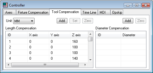
Tool length and tool diameter compensation offsets can be associated with the tool ID, or they can be defined as a simple table of offsets. When compensation is defined with respect to the tool, each offset is identified by the combination of its tool number and the offset ID for that specific tool (e.g., tool 12, offset 1). Otherwise, the compensation is defined as a simple offset ID (e.g., offset 12). Select the appropriate Add button to define the length or diameter compensation amounts for a particular offset. Tool length and diameter compensation are defined by the control emulator or post-processor, not the model. If tool length or diameter compensation is not defined in the CE or PP, then the appropriate Add button will not be available.
The offset amounts are entered and listed in the units specified in the Unit drop-down list. Double-click on an axis, diameter or corner radius entry to change its value. Use the Tab and Shift Tab keys to quickly move between entries. Press the Set button to set the offset values of the selected ID lines to the current Axes positions (as set via the Axes tab). Press the Zero button to quickly zero the offset values of the selected ID lines. You can completely remove an offset ID by selecting the entire line and pressing the Delete key.
The currently active length and diameter compensation IDs can be seen in simulation window heads-up display by activating the “Active Compensations” check box in the Simulation»Display dialog (Ctrl Alt D shortcut).
Tool compensation data is automatically saved in the verification setup (.vsw) file when the program is completed. This setup file will be reused on subsequent runs to quickly reestablish the tool compensation settings necessary for an accurate simulation.