The Rotary Axis Property Dialog
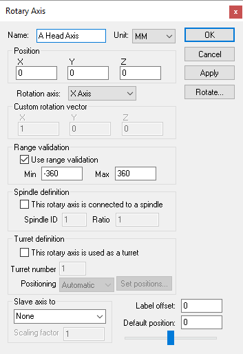 Defines a rotary axis, given an XYZ origin and the direction
vector and range of interpolation.
Defines a rotary axis, given an XYZ origin and the direction
vector and range of interpolation.
Rotation axis: The axis about which the rotation occurs. Standard rotations have the A, B and C axes rotating about the X, Y and Z axes respectively. Rotary axes that move the tool (e.g., rotary heads) typically have a standard positive direction, and those that move the part (e.g., rotary tables) have a negative (reversed) direction. For example, rotating the part in a CCLW direction has the effect of moving the tool in a CLW direction with respect to the part. Select “Custom” if the rotary axis does not rotate around one of the major axes. When Custom is selected, you must enter a Custom rotation vector, which defines the X, Y and Z-axis vector components of the axis of rotation, using the “right hand rule”. Using your right hand, point your thumb in the direction of the vector; your fingers curl in the direction of positive rotation.
Use range validation: Clear this check box if the rotary axis has unlimited physical travel.
Spindle definition: Select the “This rotary axis connects to a spindle” check box if the rotary axis can double as a spindle. This is common for mill/turn lathes, where the spindle can freely rotate when turning but then be interpolated as a rotary axis when milling. VM uses the Spindle ID to differentiate between the different spindles that might be available on a machine. Once defined, a spindle can be later mapped as a milling or turning spindle using the Axes mapping tab page of the machine properties dialog. Ratio can be specified if the spindle rotation is not 1:1.
Turret definition: Select the “This rotary axis is used as a turret” check box if the rotary axis defines the rotation of a lathe tool turret. VM uses the Turret number to differentiate between the different turrets that might be available on a machine. Turret number 1 should be used for the main turret. Turret number 2 should be used for a second turret if one exists. The Positioning field is used by VM to position the turrets as tools are loaded. With Automatic positioning, the turret is expected to have the available tool slots equally distributed around the perimeter. Use Predefined positioning and select the Set positions button to define the turret rotation angle for each of the available tool slots.
Label offset: Defines the offset of the informational kinematics marker along the rotation axis. Kinematics markers can be enabled or disabled using the VM Grid tool bar.
When defining a rotary axis with a Custom orientation, you can enter the custom rotation vector, or you can use a standard orientation and use the Rotate button to orient the axis. Both methods produce identical kinematics, but the Rotate method has the side effect of changing the XYZ reference coordinates for any objects attached to the axis.
Movable axes also share the following additional parameters:
Range: Specifies the Minimum and Maximum travel extent of the axis with respect to the axis origin position. The range does not have to include the zero position.
Slave axis to: Specifies the name of another axis that will be used to control the current one. When the named axis moves, the current axis will also be moved. You can specify a Scaling factor to change the proportion of motion, and even the direction (by specifying a negative scale factor). An axis that is slaved will not appear in the QUEST lower right Axes window or the VM Controller Axes window in CERUN and GENER. Motion of a slaved axis is only possible by moving the parent axis (i.e., the one the axis is slaved to).
Default position: Specifies the position the axis will be set to when the model is loaded, or when the axis position is reset to its default.
When you add a new axis, it will appear in the lower right “Axes” window. The axis name will also appear in the Model Navigator, attached as a child (below) the object that was selected (in the Navigator) when the axis was created. You can move the axis to a new position in the Navigator by first selecting it with the mouse, then, while holding the left-mouse button down, move to a new attachment point and release the mouse button. Moving the axis name in the model navigator may change the kinematics of the machine.
In addition to the parameters listed above, all axes share the common parameters, listed below:
Name: Axis names are used in the Model Navigator in QUEST. Linear, Rotary and Curve axis names also appear in (and can be controlled from) the QUEST lower right Axes window as well as the VM Controller Axes window in CERUN and GENER VM assigns default names when objects are created. You should change the default to something that is both short and meaningful.
Unit: Specifies the unit of measure for all non-rotary values (angles are always specified in degrees).
Position: Specifies the X, Y and Z axis position of the origin of the current axis in relation to the origin and rotational alignment of the parent object. When world coordinates are selected (Simulation»Use World CS), the position of the axis is shown in world coordinates instead of relative to the parent object. When constructing an axis, the mouse pointer can be used to define the axis origin.
OK button: Creates the axis as defined.
Cancel button: Ignores this axis creation request.
Apply button: Updates the simulation window to show the effects of the latest changes.
Rotate button: Use this button to rotate the entity to its required final orientation. When an entity is rotated, anything attached below this entity in the Navigator will be defined in the new frame of rotation.