Virtual Machine
Adding Parts, Fixtures and Stock to the Simulation
An accurate simulation must include the part(s) being manufactured, so that VM can test for gouging with the cutting portion of the tool and collisions between the part and the tools, holders and other components of the machine. The part holding fixture(s) should also be included in the simulation, again so that VM can accurately test for collisions. Finally, when the Material Removal Simulation (MRS) license option is available, the rough stock can be added to the simulation to verify in-process stock removal and collisions against the in-process stock. Even without the MRS option, adding stock to the simulation can aid in viewing the cutting process.
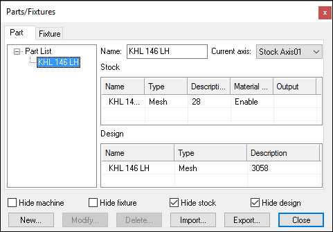
Select Simulation»Parts/Fixtures (Ctrl Alt P) to activate the Part/Fixtures dialog. You use this dialog to import STL definitions of the design part, rough stock and holding fixtures. You can also use the rudimentary design capabilities available with this dialog to interactively create simple part, stock and fixture components if needed (this process is described further on in this section).
Parts can be composed of both a rough stock, used for material removal simulation, and the design part, to which it can be compared using the Simulation»Compare (Ctrl Alt Q) function. Fixtures can be composed of both machinable and non-machinable components.
The part, stock and fixture information is automatically saved in the verification setup (.vsw) file when the program is completed. This verification setup file will be reused on subsequent runs to quickly reestablish the material conditions necessary for an accurate simulation.
The Export button on the Parts/Fixtures dialog can be used to save the current setup as a 3D model (.m3d1) file. The Import button can be used to merge the part/fixture/stock setup of a selected 3D model or verification setup file into the current session. Use the Export and Import functions to quickly copy the stock, fixture and part setup from one program to another.
If stock is defined with the "Material Removal" property enabled, then the Export function will also prompt to save resulting in-process stock as an STL (.stl) file. In-process stock can also automatically be saved at the end of processing by specifying a file name for the in-process stock "Output" property.
Differences between Part, Stock and Fixture Components
Part, stock and fixture components are all treated differently in VM during collision testing. The differences are as follows:
Part»Design: The cutting portion of the tool can interfere (without diagnostics) with the design part, to the extent of the gouge tolerance. The gouge tolerance amount is defined in the Simulation»Options dialog Tolerances tab. Some gouging is to be expected, due to the effects of the manufacturing tolerance used by the CAM system when creating the tool path and the tolerance used in the creation of the STL part model. If CAM manufacturing and STL tolerances are not adjusted, the gouge tolerance should not have to be changed from one part to the next. The non-cutting portion of the tool, the tool holder and all other collision-enabled components of the machine are also tested for collision with the design part. The gouge tolerance is not applied when testing for part collision with these components.
Part»Stock: With the Material Removal Simulation (MRS) license option enabled, VM can compute the in-process state of the raw stock. The path of the cutting portion of the tool will be "subtracted" from the stock during the manufacturing process in the same way that material is removed during real machining. Motions that cut the stock at rapid or while the spindle is stopped, will be diagnosed with an error. These cuts will also appear highlighted on the in-process stock object and identified as a collision in the Timeline display. Individual components of the stock can be enabled or disabled for MRS simulation using the component's Material Removal column setting. If an MRS license is not available or not enabled, any object defined as stock is shown in the Simulation window but ignored for collision testing purposes. To enable collision testing on a near-net stock shape, define it instead as machinable fixture. This will allow only the cutting portion of the tool to interfere with the stock provided that the motion is at feed and the spindle is turning.
Fixture: Individual components of a fixture can be identified as machinable or not, which affects how they are tested for collisions. A machinable component might be a "soft" clamp or plate that will be cut by the tool during the manufacturing process. With the Material Removal Simulation (MRS) license option enabled, VM can optionally compute the in-process state of machinable fixture components, treating them as though they were defined as stock objects (see stock definition above). If an MRS license is not available, or is not enabled for a machinable fixture component, then the cutting portion of the tool is not tested for collision with the fixture component if the tool is spinning and the cutting motion is at feed. The non-cutting portion of the tool, the tool holder and all other collision- enabled components of the machine are always tested for collision with machinable fixture components. Non-machinable fixture components are always tested for collision against the entire tool, the tool holder and all other collision-enabled components of the machine.
VM does not check for interference between part and fixture, so they can partially or completely overlap each other without problems.
Collision testing is performed by sampling the motions of the machine along the tool path. The rate of sampling, called the collision tolerance, is defined in the Simulation»Options dialog. This collision tolerance value should match the finest CAM manufacturing tolerance used in the part program. The collision tolerance is a modal value stored in the registry; it is not stored on a program-by-program basis in the verification setup (.vsw) file.