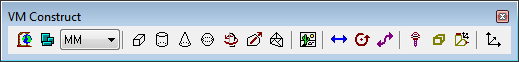
VM Construct Toolbar
|
Simulation»Use World CS: When selected, object coordinates are listed in world coordinates, originating from the center of the grids. When unselected, an object?s coordinates are listed relative to its parent (i.e., in local coordinates). This button also affects the placement of objects copied from one place to another in the model navigator. When world coordinates are selected, the object retains its position despite being moved or copied from one place to another in the navigator hierarchy. When local coordinates are selected, the object is placed relative to its new parent at the same offset it was originally at relative to its old parent. |
|
Simulation»Group Selection: When selected, picking any component of a group will select the entire group. Objects can be grouped into larger components, for selection purposes, in the 3D Models»Groups»Selection section of the model navigator. |
|
Simulation»Construct Entity»Cube: Creates a cubic entity, given an XYZ origin and the width, length and height of the cube. Once created, the cube can be further rotated to the required orientation. |
|
Simulation»Construct Entity»Cylinder: Creates a cylindrical entity, given an XYZ origin and the radius and height of the cylinder. Once created, the cylinder can be further rotated to the required orientation. The starting and ending radii can also be modified. |
|
Simulation»Construct Entity»Cone: Creates a conical entity, given an XYZ origin, base radius and height of the cone. Once created, the cone can be further rotated to the required orientation. The starting and ending radii can also be modified. |
|
Simulation»Construct Entity»Sphere: Creates a spherical entity, given an XYZ origin and radius of the sphere. Once created, the sphere can be further rotated to the required orientation. The “number of subdivisions” controls the smoothness of the sphere, with a value 0 producing a (20 face) icosahedron, and increasing subdivisions increases the faces by a factor of 3. A maximum of 6 subdivisions is permitted (very CPU intensive). |
|
Simulation»Construct Entity»Revolved: Sweeps a 2D profile over a complete or partial arc to produce a surface of revolution. The profile is defined as a series of (radius, height) pairs of coordinates, which is swept around the Z-axis. Once created, the surface can be further rotated to the required orientation. |
|
Simulation»Construct Entity»Extruded: Sweeps a 2D closed profile along a vector to produce an extruded surface. The profile is defined as a series of (x, y) pairs of coordinates, joined at the start an end, which is extruded along a vector (positive Z by default) for a specified distance. Once created, the surface can be further rotated to the required orientation. |
|
Simulation»Construct Entity»Mesh: Imports an STL mesh into the model. Once imported, the mesh surface can be further scaled and rotated to its required size and orientation. |
|
Simulation»Construct Entity Picture: Loads a bitmap image, given the point in the model for the lower left corner of the image, and the X-axis width and Y-axis height of the image in model coordinates. The picture can be rotated to the required orientation. |
|
Simulation»Construct Axis»Linear Axis: Creates a linear axis, given a point of origin and the direction and range of motion. |
|
Simulation»Construct Axis»Rotary Axis: Creates a rotary axis, given a point of origin, the rotation axis and an optional range of motion. |
|
Simulation»Construct Axis»Curve Axis: Creates a curved axis, given a point of origin and an open or closed 2D profile. The profile is defined as a series of (x, y) pairs of coordinates. The curved axis can be further rotated the required orientation. |
|
Simulation»Construct Axis»Tool Axis: Creates a tool reference point that can identify one of: the SCP of the machine, a specific pocket in the tool changer, or other named places where tools might be attached. |
|
Simulation»Construct Axis»Stock Axis: Creates a part reference point that identifies where fixtures and parts are loaded on the machine. |
|
Simulation»Construct Axis»Head Axis: Creates a head reference point that can identify one of: the head attachment point on the machine, head storage locations for inactive heads, and other places where heads might be attached. |
|
Simulation»Construct Axis»Reference Axis: Creates a reference point in the model. Reference points are used to group related entities. |


