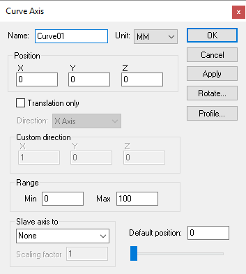
The Curve Axis Property Dialog
 Defines a curved profile axis, given an XYZ origin and a
profile curve. Curved axes can be used to interpolate along an opened or
closed track.
Defines a curved profile axis, given an XYZ origin and a
profile curve. Curved axes can be used to interpolate along an opened or
closed track.
Profile button: Select this button to enter a 2D profile curve. The profile is defined as a series of (x, y) pairs of coordinates, one pair per line. Use the Apply button in the profile builder to see changes to the profile curve.
Translation only: When a curve axis moves, the objects that are attached to it can be moved through space as a simple translation, or they can be both translated and rotated to stay “normal” to the curve.
If a single child object is attached to a curve axis, that object is attached to the curve axis origin in the standard way. If a second object is attached to the curve axis, that object is shown moved, or both moved and rotated, to the halfway point along the curve axis. The critical concept here is the word “shown”. All objects are attached to the curve axis at the origin, but they are shown equally spaced along the curve axis. Use a Reference axis to group two or more components that must be moved together along the curved axis.
Because the profile curve is defined in the XY plane, the Rotate button must be used to orient the profile to its true position. The Rotate method has the side effect of changing the XYZ reference coordinates for any objects attached to the axis. You can eliminate this effect by attaching a “Reference Axis” to the curve axis, which you can use to rotate the coordinate system back to a standard orientation.
Movable axes also share the following additional parameters:
Range: Specifies the Minimum and Maximum travel extent of the axis with respect to the axis origin position. The range does not have to include the zero position.
Slave axis to: Specifies the name of another axis that will be used to control the current one. When the named axis moves, the current axis will also be moved. You can specify a Scaling factor to change the proportion of motion, and even the direction (by specifying a negative scale factor). An axis that is slaved will not appear in the QUEST lower right Axes window or the VM Controller Axes window in CERUN and GENER. Motion of a slaved axis is only possible by moving the parent axis (i.e., the one the axis is slaved to).
Default position: Specifies the position the axis will be set to when the model is loaded, or when the axis position is reset to its default.
When you add a new axis, it will appear in the lower right “Axes” window. The axis name will also appear in the Model Navigator, attached as a child (below) the object that was selected (in the Navigator) when the axis was created. You can move the axis to a new position in the Navigator by first selecting it with the mouse, then, while holding the left-mouse button down, move to a new attachment point and release the mouse button. Moving the axis name in the model navigator may change the kinematics of the machine.
In addition to the parameters listed above, all axes share the common parameters, listed below:
Name: Axis names are used in the Model Navigator in QUEST. Linear, Rotary and Curve axis names also appear in (and can be controlled from) the QUEST lower right Axes window as well as the VM Controller Axes window in CERUN and GENER VM assigns default names when objects are created. You should change the default to something that is both short and meaningful.
Unit: Specifies the unit of measure for all non-rotary values (angles are always specified in degrees).
Position: Specifies the X, Y and Z axis position of the origin of the current axis in relation to the origin and rotational alignment of the parent object. When world coordinates are selected (Simulation»Use World CS), the position of the axis is shown in world coordinates instead of relative to the parent object. When constructing an axis, the mouse pointer can be used to define the axis origin.
OK button: Creates the axis as defined.
Cancel button: Ignores this axis creation request.
Apply button: Updates the simulation window to show the effects of the latest changes.
Rotate button: Use this button to rotate the entity to its required final orientation. When an entity is rotated, anything attached below this entity in the Navigator will be defined in the new frame of rotation.