VM Controller / Axes Tab
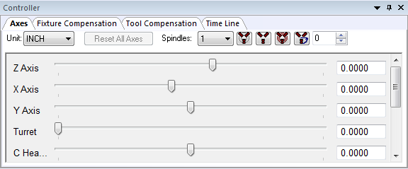
Provides interactive motion control over the axes of the model when processing is in a paused state. The sliders move each axis through its available range of travel. Linear axes positions are listed in the units selected in the Unit drop-down list. For rotary axes with unlimited travel, sliders move the axis through ?405º of travel. Axes can be moved to any position (within travel or otherwise) by entering a value in the input-field next to the slider. When the Enable tooltip check box is selected, resting the mouse pointer over an axis name, slider bar or input-field, will pop-up a tool-tip dialog showing the minimum, maximum and current axis position.
You can toggle the between machine linear axes and LCS (local coordinate system) linear positions using the Simulation»Show»Workpiece Coords (Ctrl W) menu function. When workpiece coordinates are enabled, the linear axes are labeled as “Xw”, “Yw” and “Zw” axes in both the Axes tab and in the HUD
The axes can be interactively moved to a model defined reference position (e.g., tool change or home position), by first selecting the reference by name in the Ref drop-down selection field and then pressing the button to the immediate right of the reference name.
|
Moves axes to the selected reference position. |
|
Activates a dialog to edit reference position information (QUEST only). |


Select Reset All Axes to reset all axes to the last interpolated position (i.e., to the positions they were at before they were changed via the slider or position input field). Axes are automatically reset whenever processing is continued. Note that it is not possible to interactively set an axis position and continue processing with the axis at that set position.
The spindle state can also be interactively controlled and tested from Axes tab. First, select the spindle identifier in the Spindles drop-down selection field and then press one of the buttons immediately to the right as follows:
|
Toggles on and off the selected spindle. Any objects attached to the spindle will be swept around the spindle axis to create the volume that will then be used for collision detection and material removal. When the spindle is turning, the swept volume is displayed as a solid object. When the spindle is subsequently stopped, the swept volume continues to be shown in a transparent color (representing the fact that the position of the spindle is unknown), with the unswept object shown inside for reference purposes. |
|
Stops and locks the selected spindle. |
|
Places the selected spindle in neutral. |
|
Orients the selected spindle to the angle specified in the field immediately to the right of the button. The swept profile is no longer used once a spindle is oriented, since its position is then known. |


For known robot kinematics, Shoulder Right-Left, Elbow Down-Up and Wrist Front-Rear buttons retain the tool tip position and tool orientation, but change selected robot joints to test out different possible robot configurations (8 in total) for collision avoidance and reachability purposes. These controls are available for known robots only. Send ICAM’s Support department your robot model in “dmp” format to have it enabled for configuration testing.