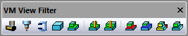
VM View Filter Toolbar
|
Simulation»Show»Filters»Machine: Toggles the display of all components defined within the model. This includes the machine, heads and any other model objects as defined and saved in the model with QUEST. |
|
Simulation»Show»Filters»Tools: Toggles the display of all tooling components defined at run-time via the Simulation»Tools (Ctrl Alt T) dialog. This includes tools and their holders, both active and inactive. |
|
Simulation»Show»Filters»Fixtures: Toggles the display of the holding devices as defined at run-time via the Simulation»Parts/Fixtures (Ctrl Alt P) dialog Fixtures tab. |
|
Simulation»Show»Filters»Stock: Toggles the display of the workpiece original un-cut raw stock as defined at run-time via the Simulation»Parts/Fixtures dialog Part tab. |
|
Simulation»Show»Filters»Parts: Toggles the display of the workpiece design part as defined at run-time via the Simulation»Parts/Fixtures dialog Part tab. |
|
Simulation»Show»Filters»In-process Stock: Toggles the display of the stock as modified by the cutting action of the tools. At the start of processing, the Stock and In-process Stock are identical, but they should be quite different by the end of processing. |
|
Simulation»Show»Filters»Stock Checkpoints: Toggles the display of the in-process stock as it appeared at earlier moments in time when moving the Time Line backwards and forwards. These earlier checkpoints can be taken at each tool change, at each operation and/or periodically during long cutting sequences as controlled from the Simulation»Options menu MRS tab “In-process stock checkpoints” settings. |
|
Simulation»Show»Filters»Boolean Overcut: Toggles the display of any gouges in the in-process stock as compared to the original part. Gouges are shown in red. VM only compares those in-process stock and part components that are associated to each other. Part/stock association is done from the Simulation»Parts/Fixtures menu. |
|
Simulation»Show»Filters»Boolean Undercut: As above, but toggles the display of excess in-process stock when compared to the original part. Excess material is shown in blue. |
|
Simulation»Show»Filters»Colorized Boolean: Modifies the color of the Boolean overcut and undercut regions, based on the thickness of the gouge or excess material. Colorized Boolean settings are controlled from the Simulation»Compare (Ctrl Alt Q) dialog. |
|
Simulation»Show»Filters»Transparent Zero: modifies the display of the colorized Boolean comparison, to show in a transparent color all faces of the object that are in the tolerance zone between gouge and excess material. This setting can be used to see a gouge or excess in the context of the entire part. |


