VM Cross Section Toolbar
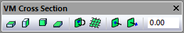
The Cross Section toolbar can be used to obtain a cross section view of the in-process stock, which is only available when the Material Removal Simulation (MRS) license option is enabled.
|
Simulation»Show»Cross Section»XY Plane: Selections cause the stock to be sectioned along the XY stock mount point plane. |
|
Simulation»Show»Cross Section»YZ Plane: Selections cause the stock to be sectioned along the YZ stock mount point plane. |
|
Simulation»Show»Cross Section»ZX Plane: Selections cause the stock to be sectioned along the ZX stock mount point plane. |
|
Simulation»Show»Cross Section»Custom Plane: Selection can be used to define a cross section plane using the Simulation»Measure picking functions. For example, a cross section plane can be defined by picking a face, or by picking 3 points that lie on the plane, etc. |
|
Simulation»Show»Cross Section»Invert Plane: This button toggles between showing the in-process stock on one side of the cross section plane or the other. |
|
Simulation»Show»Cross Section»Show Grid: This button enables or disables the display of a grid on the cross section plane. Grid settings are the same as for the Simulation Grid feature. |
|
Simulation»Show»Cross Section»Push Plane: This buttons offset the cross section plane by a fixed amount as defined in the Simulation»Options dialog Misc tab. |
|
Simulation»Show»Cross Section»Pull Plane: This buttons offset the cross section plane by a fixed amount as defined in the Simulation»Options dialog Misc tab. |
|
Plane Offset: This input field in the toolbar shows the current cross section plane offset resulting from the Push or Pull Plane functions. A value can also be entered into this field to define the required offset. |


