Virtual Machine Tooling
Adding Tooling Definitions to the Simulation
VM can attach solid model representations of tools and their holders to
the machine model when they are loaded. Once attached, they become part
of the collision detection process. When Material Removal Simulation
(MRS) is enabled, VM will modify stock and machinable fixture objects to
simulate the cutting actions of the tool. VM supports a variety of tool
types for both milling and turning applications, and can support both 2D
revolved contour or generic 3D shapes for holder definitions. Select
Simulation»
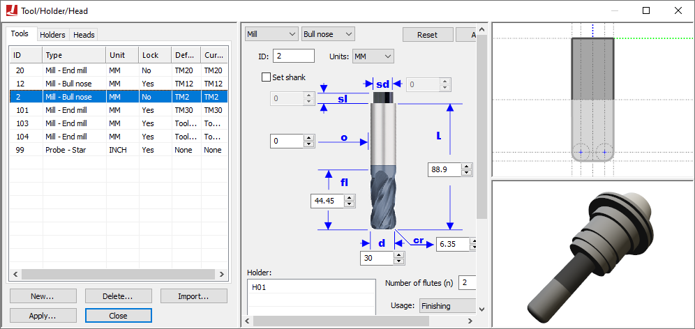
Select the Tools and Holders tabs to switch between tool and holder definitions. Select the New button to define a new tool or holder. Select an existing definition and use the central pane to make modifications; press the Apply button when done. Modified entries are listed in red until changes are applied. Select an existing definition and press the Delete button to remove it. Select the Heads tab to load or unload head attachments that are defined within the model.
All tool definitions (excluding probes) include a cutting color selection, which is used with MRS (material removal simulation) to identify surfaces on the in-process stock formed by the cutting or additive action of the tool. Tools also include a usage setting, which can override the default MRS cutting tolerance, loosening it for Semi-Finishing and Roughing tools (to reduce CPU usage).
When exiting the Tools/
Tool and holder definitions are automatically saved in the verification setup (.vsw) file when the program is completed. This setup file will be reused on subsequent runs to quickly reestablish the tooling necessary for an accurate simulation.
Icam provides “Manufacturing Extractors” for many popular CAM systems, which automatically create tool and holder definitions that match those used in the NC program.