The Tool Axis Property Dialog
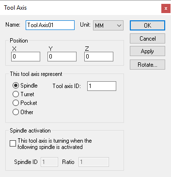 Defines a tool axis, given an XYZ origin and tool reference
type. Tool axes can define the spindle control point of the machine,
pockets in a tool changer, or anywhere else that tools might be stored.
Defines a tool axis, given an XYZ origin and tool reference
type. Tool axes can define the spindle control point of the machine,
pockets in a tool changer, or anywhere else that tools might be stored.
Spindle: Specifies that this tool axis defines the spindle control point (SCP) of the machine. The Tool axis ID should be set to 1 (one) for the main spindle of the machine. Other tool ID’s can be used if there are additional controllable spindles on the machine. The tool axis ID to use for a given tool can be selected in the model Load Tool Event macro.
Turret: Specifies that this tool axis defines one of a series of available tool mount positions arrayed on a lathe turret. The Tool axis ID should be set to 1 (one) for the main turret of the machine. Set the ID to 2 for the side turret of the machine. The Pocket ID is used by VM to know which turret position is active based on the current tool selected. Pocket numbers must be unique for each turret.
Pocket: Specifies that this tool axis defines a pocket in the tool changer or some other holding area. A Pocket ID must be given to identify the pocket number. VM automatically moves tools in and out of pockets during tool change operations. Use the CERUN and GENER Simulation»Tools menu to assign tools to pockets.
Other: Specifies a location where tools can be held. A typical use for this type of tool axis is to define a position on a tool change mechanism where tools are held while in transit. Tools can be attached or detached from an “other” axis type using the $FMSATA macro function.
Spindle activation: Select the “This tool axis is turning when the following spindle is activated” check box if the tool axis represents a spindle. This is common for the spindle on milling machines, and for live tooling on mill/turn machines. You would normally not select this for a Pocket or Other tool axis type. VM uses the Spindle ID to differentiate between the different spindles that might be available on a machine. For mill/turn machines, use the Axes mapping tab page of the machine properties dialog to identify the spindle as milling or turning. For milling machines, the spindle ID should be 1 (one) for the main spindle of the machine. The choice of current active spindle can also be controlled using the $FMSMSP macro function.
Use the Rotate button to establish the orientation of the tool when it is attached to the tool axis object.
Note that, for QUEST at least, the tool axis represents one end of the kinematics chain. You cannot attach any other axis or entity to a tool axis. CERUN and GENER on the other hand allow holders and tools to be attached to a tool axis at run-time.
In addition to the parameters listed above, all axes share the common parameters, listed below:
Name: Axis names are used in the Model Navigator in QUEST. Linear, Rotary and Curve axis names also appear in (and can be controlled from) the QUEST lower right Axes window as well as the VM Controller Axes window in CERUN and GENER VM assigns default names when objects are created. You should change the default to something that is both short and meaningful.
Unit: Specifies the unit of measure for all non-rotary values (angles are always specified in degrees).
Position: Specifies the X, Y and Z axis position of the origin of the current axis in relation to the origin and rotational alignment of the parent object. When world coordinates are selected (Simulation»Use World CS), the position of the axis is shown in world coordinates instead of relative to the parent object. When constructing an axis, the mouse pointer can be used to define the axis origin.
OK button: Creates the axis as defined.
Cancel button: Ignores this axis creation request.
Apply button: Updates the simulation window to show the effects of the latest changes.
Rotate button: Use this button to rotate the entity to its required final orientation. When an entity is rotated, anything attached below this entity in the Navigator will be defined in the new frame of rotation.