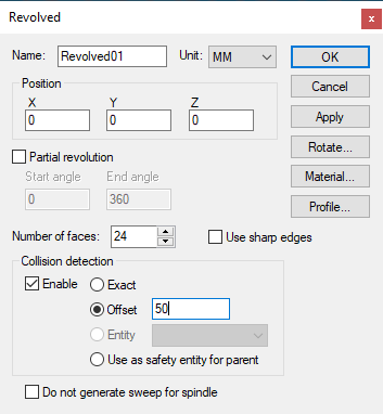
The Revolved Property Dialog
 Defines a swept 2D profile over a complete or partial arc to
produce a surface of revolution. Once created, the surface can be
further rotated to its required orientation using the Rotate button.
Defines a swept 2D profile over a complete or partial arc to
produce a surface of revolution. Once created, the surface can be
further rotated to its required orientation using the Rotate button.
Partial revolution: If selected the profile will be rotated between the Start angle and End angle positions. When not selected, a complete 360° arc is used.
Profile button: Select this button to enter the surface profile. The profile is defined as a series of (radius, height) pairs of coordinates, one pair per line, which is swept around the Z-axis. The order in which points are defined is important; the outside surface of the profile is to the left of the curve defined by the points. The profile does not have to be closed (i.e., it does not have to start and end at the same point). Use the Apply button in the profile builder to see changes to the profile curve.
Entities that represent curved shapes are approximated by faceted surfaces. The following parameters are used for curved entities:
Number of faces: Specifies the number of facets to use to approximate a curved surface. The greater the number of facets, the smoother the surface will appear. Note that the trade-offs for smooth appearance are a longer rendering time and a higher CPU cost for collision detection.
Use sharp edges: Specifies how the object should be drawn. When sharp edges are used, the profile will appear with clearly defined edges. When smooth edges are used, the graphic engine will attempt to blend the edges, smoothing them out. You can get surprisingly smooth looking surfaces even with coarse faceting.
In addition to the parameters listed above, all entities share the common parameters, listed below:
Name: Entity names are used in the Model Navigator in QUEST, and in collision diagnostic messages in CERUN and GENER. VM assigns default names when objects are created. You should change the default to something that is both short and meaningful.
Unit: Specifies the unit of measure for all non-rotary values (angles are always specified in degrees).
Position: Specifies the X, Y and Z axis position of the origin of the current object in relation to the origin and rotational alignment of the parent object. When world coordinates are selected (Simulation»Use World CS), the position of the entity is shown in world coordinates instead of relative to the parent object. When constructing an entity, the mouse pointer can be used to define the entity start position (and other parameters as well).
Collision detection: Select the Enable check box to activate collision testing against the current entity. Collision detection can be done using one of the following method:
Exact: Collision is performed on the exact geometry of Entity
Offset: An offset value is applied to the entity mesh and used as safety zone for collision
Entity: Another entity is used as the the safety zone for this entity. Valid entities must be direct child without children of their own and they must not be part of any group. Valid entities are listed in the drop down box.
Use as safety entity for parent: The entity is used as the safety zone for the parent. The parent property dialog will show collision using this entity as safety zone.
Collision type is remembered even if the entity is disabled from collision. The collision type will be used if the entity gets re-enabled for collision dynamically by macro. You can see the extended collision envelope of all entities by toggling Simulation »Show»Safety zones from the menu bar.
OK button: Creates the entity as defined.
Cancel button: Ignores this entity creation request.
Apply button: Updates the simulation window to show the effects of the latest changes.
Rotate button: Use this button to rotate the entity to its required final orientation. When an entity is rotated, anything attached below this entity in the Navigator will be defined in the new frame of rotation.
Material button: Use this button to define the appearance (color) of the object. Material properties are described later under the topic “Materials Dialog". Objects are by default created using the material of the last object created or selected using the Materials Dialog (Ctrl Alt M shortcut).