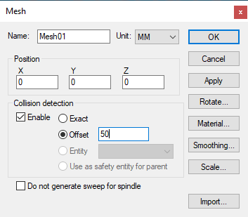
The Mesh Property Dialog
 Defines an imported STL mesh into the model. Once imported, the
mesh surface can be further rotated to its required orientation using
the Rotate button.
Defines an imported STL mesh into the model. Once imported, the
mesh surface can be further rotated to its required orientation using
the Rotate button.
Import button: Select this button to choose the STL file to be imported. An STL file does not define its units of measure; use the Units field on the STL import dialog to specify the dimensional units of the file. The import dialog also provides a File format field to specify the STL file format. Normally the default Auto selection should suffice; but if you have difficulty importing an STL file, try selecting other file formats.
Smoothing button: Select this button to improve the appearance of facetted surfaces by using smooth light rendering at edges having a change of angle within a specified amount.
Scale button: Use this button to scale the STL mesh object if the object as imported is the wrong size. Alternately, you could import the object again this time specifying different dimensional units.
In addition to the parameters listed above, all entities share the common parameters, listed below:
Name: Entity names are used in the Model Navigator in QUEST, and in collision diagnostic messages in CERUN and GENER. VM assigns default names when objects are created. You should change the default to something that is both short and meaningful.
Unit: Specifies the unit of measure for all non-rotary values (angles are always specified in degrees).
Position: Specifies the X, Y and Z axis position of the origin of the current object in relation to the origin and rotational alignment of the parent object. When world coordinates are selected (Simulation»Use World CS), the position of the entity is shown in world coordinates instead of relative to the parent object. When constructing an entity, the mouse pointer can be used to define the entity start position (and other parameters as well).
Collision detection: Select the Enable check box to activate collision testing against the current entity. Collision detection can be done using one of the following method:
Exact: Collision is performed on the exact geometry of Entity
Offset: An offset value is applied to the entity mesh and used as safety zone for collision
Entity: Another entity is used as the the safety zone for this entity. Valid entities must be direct child without children of their own and they must not be part of any group. Valid entities are listed in the drop down box.
Use as safety entity for parent: The entity is used as the safety zone for the parent. The parent property dialog will show collision using this entity as safety zone.
Collision type is remembered even if the entity is disabled from collision. The collision type will be used if the entity gets re-enabled for collision dynamically by macro. You can see the extended collision envelope of all entities by toggling Simulation »Show»Safety zones from the menu bar.
OK button: Creates the entity as defined.
Cancel button: Ignores this entity creation request.
Apply button: Updates the simulation window to show the effects of the latest changes.
Rotate button: Use this button to rotate the entity to its required final orientation. When an entity is rotated, anything attached below this entity in the Navigator will be defined in the new frame of rotation.
Material button: Use this button to define the appearance (color) of the object. Material properties are described later under the topic “Materials Dialog". Objects are by default created using the material of the last object created or selected using the Materials Dialog (Ctrl Alt M shortcut).