The Linear Axis Property Dialog
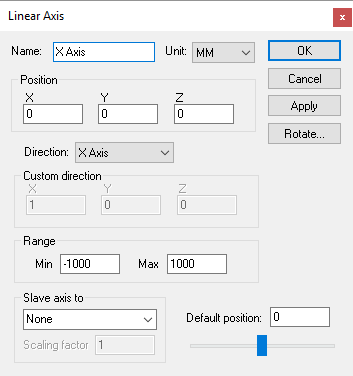 Defines a linear axis, given an XYZ origin and the direction
vector and range of interpolation.
Defines a linear axis, given an XYZ origin and the direction
vector and range of interpolation.
Direction: The direction of interpolation. Linear axes that move the tool typically have a standard positive direction, and those that move the part have a negative (reversed) direction, For example, moving the part in the negative X direction has the effect of moving the tool in the positive X direction with respect to the part. Select “Custom” if the linear axis does not interpolate along one of the major axes. When Custom is selected, you must enter a Custom direction, which defines the positive sense of interpolation given its X, Y and Z-axis vector components (the values do not have to be unitized).
When defining a linear axis with a Custom orientation, you can enter the custom direction vector, or you can use a standard orientation and use the Rotate button to orient the axis. Both methods produce identical kinematics, but the Rotate method has the side effect of changing the XYZ reference coordinates for any objects attached to the axis.
Movable axes also share the following additional parameters:
Range: Specifies the Minimum and Maximum travel extent of the axis with respect to the axis origin position. The range does not have to include the zero position.
Slave axis to: Specifies the name of another axis that will be used to control the current one. When the named axis moves, the current axis will also be moved. You can specify a Scaling factor to change the proportion of motion, and even the direction (by specifying a negative scale factor). An axis that is slaved will not appear in the QUEST lower right Axes window or the VM Controller Axes window in CERUN and GENER. Motion of a slaved axis is only possible by moving the parent axis (i.e., the one the axis is slaved to).
Default position: Specifies the position the axis will be set to when the model is loaded, or when the axis position is reset to its default.
When you add a new axis, it will appear in the lower right “Axes” window. The axis name will also appear in the Model Navigator, attached as a child (below) the object that was selected (in the Navigator) when the axis was created. You can move the axis to a new position in the Navigator by first selecting it with the mouse, then, while holding the left-mouse button down, move to a new attachment point and release the mouse button. Moving the axis name in the model navigator may change the kinematics of the machine.
In addition to the parameters listed above, all axes share the common parameters, listed below:
Name: Axis names are used in the Model Navigator in QUEST. Linear, Rotary and Curve axis names also appear in (and can be controlled from) the QUEST lower right Axes window as well as the VM Controller Axes window in CERUN and GENER VM assigns default names when objects are created. You should change the default to something that is both short and meaningful.
Unit: Specifies the unit of measure for all non-rotary values (angles are always specified in degrees).
Position: Specifies the X, Y and Z axis position of the origin of the current axis in relation to the origin and rotational alignment of the parent object. When world coordinates are selected (Simulation»Use World CS), the position of the axis is shown in world coordinates instead of relative to the parent object. When constructing an axis, the mouse pointer can be used to define the axis origin.
OK button: Creates the axis as defined.
Cancel button: Ignores this axis creation request.
Apply button: Updates the simulation window to show the effects of the latest changes.
Rotate button: Use this button to rotate the entity to its required final orientation. When an entity is rotated, anything attached below this entity in the Navigator will be defined in the new frame of rotation.