The Head Axis Property Dialog
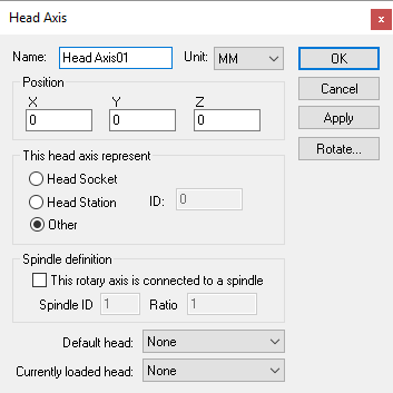 Creates a head axis, given an XYZ origin and head reference
type. Head axes can define the location on the machine where
exchangeable heads are mounted; positions on or around the machine where
heads are stored when not in use; or anywhere else where heads might be
attached.
Creates a head axis, given an XYZ origin and head reference
type. Head axes can define the location on the machine where
exchangeable heads are mounted; positions on or around the machine where
heads are stored when not in use; or anywhere else where heads might be
attached.
Head Socket: Specifies that this head axis defines the head control point (HCP) of the ma-chine. The Socket ID should be set to 1 (one) for the main head control point of the machine. Other head ID?s can be used if there are additional head mount points on the machine. The head axis ID to use for a given head can be selected in the model Load Tool Event macro.
Head Station: Specifies that this head axis defines a station in the head changer or some other holding area for head devices. A Station ID must be given to identify the station number. VM automatically moves heads in and out of stations during head change operations. Use the CERUN and GENER Simulation»Heads menu to assign heads to stations.
Other: Specifies a location where heads can be held. A typical use for this type of head axis is to define a position on a head change mechanism where heads are held while in transit. Heads can be attached or detached from an “other” axis type using the $FMSATA macro function.
Spindle definition: Select the “This head axis is connected to a spindle” check box if the head axis transmits the spindle force to attached head devices. This is common for the main head Socket. You would normally not select this for a Station or Other head axis type. VM uses the Spindle ID to differentiate between the different spindles that might be available on a machine. For mill/turn machines, use the Axes mapping tab page of the machine properties dialog to identify the spindle as milling or turning. For milling machines, the spindle ID should be 1 (one) for the main spindle of the machine. The choice of current active spindle can also be controlled using the $FMSMSP macro function.
Default head: Select the head device that will be attached to the head axis by default at the start of processing. This can be used to define the initial layout of heads at their pre-defined head stations if required. Changing the default head does not affect the current state of the model as shown in QUEST.
Currently loaded head: Use this to test the head processing of the model. Loading a head into a station will adjust the model navigator tree to show the selected head attached to the head axis. It will also draw the head at the head attachment axis. Only one head can be attached to a head axis at a time.
Use the Rotate button to establish the orientation of the head when it is attached to the head axis object.
In addition to the parameters listed above, all axes share the common parameters, listed below:
Name: Axis names are used in the Model Navigator in QUEST. Linear, Rotary and Curve axis names also appear in (and can be controlled from) the QUEST lower right Axes window as well as the VM Controller Axes window in CERUN and GENER VM assigns default names when objects are created. You should change the default to something that is both short and meaningful.
Unit: Specifies the unit of measure for all non-rotary values (angles are always specified in degrees).
Position: Specifies the X, Y and Z axis position of the origin of the current axis in relation to the origin and rotational alignment of the parent object. When world coordinates are selected (Simulation»Use World CS), the position of the axis is shown in world coordinates instead of relative to the parent object. When constructing an axis, the mouse pointer can be used to define the axis origin.
OK button: Creates the axis as defined.
Cancel button: Ignores this axis creation request.
Apply button: Updates the simulation window to show the effects of the latest changes.
Rotate button: Use this button to rotate the entity to its required final orientation. When an entity is rotated, anything attached below this entity in the Navigator will be defined in the new frame of rotation.