The Extruded Property Dialog
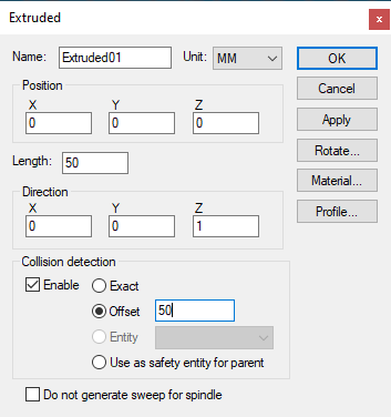 Defines a swept 2D closed profile along a vector to produce an
extruded surface. Once created, the surface can be further rotated to
its required orientation using the Rotate button. See Construct
Entity for a description of
parameters and controls not listed below.
Defines a swept 2D closed profile along a vector to produce an
extruded surface. Once created, the surface can be further rotated to
its required orientation using the Rotate button. See Construct
Entity for a description of
parameters and controls not listed below.
Length: Specifies the distance to sweep the profile along the vector defined by the direction components.
Direction: Specifies the XYZ components of the vector to sweep the profile along.
Profile button: Select this button to enter the surface profile. The profile is defined as a series of (x, y) pairs of coordinates, one pair per line, which is extruded along a vector (positive Z by default) for the specified distance. The order in which points are defined is important; the outside surface of the profile is to the left of the curve defined by the points. The profile must be closed (i.e., it must start and end at the same point). You can specify one or more additional “island” contours to be subtracted from the main extruded shape by first specifying a semicolon “;” contour separator followed by the series of (x, y) pairs of coordinates of the island contour, one pair per line. Use the Apply button in the profile builder to see changes to the profile curve.
In addition to the parameters listed above, all entities share the common parameters, listed below:
Name: Entity names are used in the Model Navigator in QUEST, and in collision diagnostic messages in CERUN and GENER. VM assigns default names when objects are created. You should change the default to something that is both short and meaningful.
Unit: Specifies the unit of measure for all non-rotary values (angles are always specified in degrees).
Position: Specifies the X, Y and Z axis position of the origin of the current object in relation to the origin and rotational alignment of the parent object. When world coordinates are selected (Simulation»Use World CS), the position of the entity is shown in world coordinates instead of relative to the parent object. When constructing an entity, the mouse pointer can be used to define the entity start position (and other parameters as well).
Collision detection: Select the Enable check box to activate collision testing against the current entity. Collision detection can be done using one of the following method:
Exact: Collision is performed on the exact geometry of Entity
Offset: An offset value is applied to the entity mesh and used as safety zone for collision
Entity: Another entity is used as the the safety zone for this entity. Valid entities must be direct child without children of their own and they must not be part of any group. Valid entities are listed in the drop down box.
Use as safety entity for parent: The entity is used as the safety zone for the parent. The parent property dialog will show collision using this entity as safety zone.
Collision type is remembered even if the entity is disabled from collision. The collision type will be used if the entity gets re-enabled for collision dynamically by macro. You can see the extended collision envelope of all entities by toggling Simulation »Show»Safety zones from the menu bar.
OK button: Creates the entity as defined.
Cancel button: Ignores this entity creation request.
Apply button: Updates the simulation window to show the effects of the latest changes.
Rotate button: Use this button to rotate the entity to its required final orientation. When an entity is rotated, anything attached below this entity in the Navigator will be defined in the new frame of rotation.
Material button: Use this button to define the appearance (color) of the object. Material properties are described later under the topic “Materials Dialog". Objects are by default created using the material of the last object created or selected using the Materials Dialog (Ctrl Alt M shortcut).