Adding Parts, Fixtures and Stock to the Simulation
An accurate simulation must include the part(s) being manufactured, so that VM can test for gouging with the cutting portion of the tool and collisions between the part and the tools, holders and other components of the machine. The part holding fixture(s) should also be included in the simulation, again so that VM can accurately test for collisions. Finally, when a Material Removal Simulation (MRS) license option is available, the rough stock can be added to the simulation to verify in-process stock removal and collisions against the in-process stock. Even without the MRS option, adding stock to the simulation can aid in viewing the cutting process.
Select Simulation»
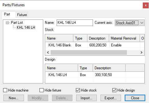
Parts can be composed of both a rough stock, used for material removal
simulation, and the design part, to which it can be compared using the
Simulation»
The part, stock and fixture information is automatically saved in the verification setup (.vsw) file when the program is completed. This verification setup file will be reused on subsequent runs to quickly reestablish the material conditions necessary for an accurate simulation.
The Export button on the Parts/
If stock is defined with the “Material Removal” property enabled, then the Export function will also prompt to save resulting in-process stock as an STL (.stl) file. In-process stock can also automatically be saved at the end of processing by specifying a file name for the in-process stock “Output” property.
Differences between Part, Stock and Fixture Components
Part, stock and fixture components are all treated differently in VM
during collision testing.
See Simulation»
Part»
Stock: Represents the uncut material at the start of an operation. Stock definitions are ignored for collision testing purposes unless running with the Material Removal Simulation (MRS) license option enabled. Part»
Design: Represents the final shape expected to be produced. Collision testing is always enabled, with an additional allowable gouge tolerance on the cutting portion of the tool. Fixture: Represents the part holding device. Two forms of collision testing are enabled, depending on whether the fixture is machinable or not.
Creating Part, Stock and Fixture Components
The Parts/Fixtures dialog tabs provide similar features. Objects are listed in a scrolling list. New objects can be added and old ones deleted or modified. Objects can be given names, which are used by VM when reporting collision diagnostic messages. Adding an object is a two-step process. The first step is to create a new object, defining its name and where (roughly speaking) it will be loaded on the machine. The second step is to actually define the physical components and placement of the object. The simulation window remains active when defining part, stock and fixtures, to permit interactive creation and placement of objects.
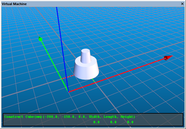
For example, follow the steps below to create a rectangular base plate, whose lower left corner is (X–200, Y–150, Z0) with a length of 400, width of 300 and height of 25 (all dimensions in mm):
Step 1: Create a new fixture object
Step 1: Create a new fixture object
Select the Fixture tab.
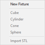
Select the New button and then select the New Fixture sub-menu option.
Type in the name of the new item, e.g., “Base plate”. This name will be used by VM when reporting collisions between this and other objects.
Objects are always created relative to one or more standard stock axes defined by the model creator. If there are multiple stock axes (for example, two pallets), then you can specify where the base plate will be mounted using the Axis drop-list. The “None” choice can be used to remove a component from the machine once you have finished defining it. You can change the default mount point and current mount points.
Step 2: Define the physical components of the new fixture object
Step 2: Define the physical components of the new fixture object
Select “Base plate” in the Fixture tab component tree list.
Select the New button and then select the Cube sub-menu option.
Type, in order: –200 Enter –150 Enter 0 Enter 400 Enter 300 Enter 25 Enter
When defining the physical components of an object, the component type
(e.g. “Cube”) and its required parameters (e.g., x, y, z, width, length
and height) are listed at the bottom of the simulation window. You can
enter the parameters using the keyboard as instructed above, or you can
move the mouse to an appropriate position and click the left-mouse
button. Each click of the mouse can supply values for one or two
parameters, which will be dynamically updated as you move the mouse.
Hold the Shift key to toggle the snap-to-grid feature of the mouse. Use
the grid button toggle on the VM Grid toolbar or select Simulation»
Use the mouse pointer or keyboard to set parameter values.
Use the left-mouse-button or Enter key to accept a parameter value and move to the next input field.
Use the Tab and Shift Tab keys to move forward and backward through the required parameters without making changes.
Use the Shift key, VM Grid toolbar or Simulation»
Grid dialog to change grid settings.
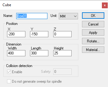
Once a component is created, it can be given a name, rotated, repositioned, resized and have its visual material properties set.
The component name will be used in combination with the object name (e.g., “Base plate Box01”) in collision diagnostics. The name can be omitted if desired, and the same name can be repeated for other components.
Press the Apply button to immediately see the effects in the simulation window of any repositioning or re-dimensioning of the component. All dimensions are expressed in the units listed in the unit drop-down choice list. The units can be changed, with the option of either readjusting the object’s size to match or not.
You can repeatedly select the Rotate button to define a compound rotation of the component. The Reset choice removes any rotation previously added.
Press the Material button to activate the Materials Dialog, which defines the component’s appearance. There are three color selections that can be associated with a material, in addition to its general shininess and transparency: The Diffuse component is the color of the object. The Ambient component is the color of light that indirectly strikes the object (for example, the color of the walls). The Specular component is mixed with the color of the main light sources to produce the highlights visible as shininess is increased. You can simplify the material property selection by choosing one from the drop-down list of predefined materials.
Press the OK button when done.
The new Box01 entity will now appear in the list of components that make up the fixture object. For fixture components that are expected to be cut during the manufacturing process (e.g., a base plate or soft block), select Yes in the Machinable column in the fixture component list. By default, fixture components are not machinable. For stock and machinable fixture components, you must select No in the Material Removal column to disable material removal simulation (requires an MRS license option), since by default, MRS simulation is enabled for stock and machinable fixture components.