Simulation»
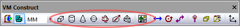
Provides the ability to add physical entities (i.e., things you can see) to the model. This menu selection is only available in QUEST. The “Machines” section must be opened before you can add entities to the model. The VM Construct tool bar provides buttons (as shown circled above) for each of the entities that can be constructed.
All entities share some common parameters, listed below:
Name: Entity names are used in the Model Navigator in QUEST, and in collision diagnostic messages in GENER and CERUN. VM assigns default names when objects are created. You should change the default to something that is both short and meaningful.
Unit: Specifies the unit of measure for all non-rotary values (angles are always specified in degrees).
Position: Specifies the X, Y and Z axis position of the origin of the current object in relation to the origin and rotational alignment of the parent object. When world coordinates are selected (Simulation»
Use World CS), the position of the entity is shown in world coordinates instead of relative to the parent object. When constructing an entity, the mouse pointer can be used to define the entity start position (and other parameters as well). Collision detection: Select the Enable checkbox to activate collision testing against the current entity. A Safety zone amount can be specified when collision checking is enabled, which checks for a collision at the specified distance from the surface. You can see the extended collision envelope of all entities by toggling Simulation»
Show» Safety Zones from the menu bar. Spindle sweep: Select the “Do not generate sweep for spindle” checkbox to exclude the entity from spindle sweep volume calculations, which dynamically compute the swept volume of objects attached to a turning spindle for visualization and collision detection purposes. Excluding an object from spindle sweep calculations will reduce the CPU overhead of these calculations, but at the same time will omit the object for collision and visualization purposes while the spindle to which it is attached is turning.
OK button: Creates the entity as defined.
Cancel button: Ignores this entity creation request.
Apply button: Updates the simulation window to show the effects of the latest changes.
Rotate button: Use this button to rotate the entity to its required final orientation. When an entity is rotated, anything attached below this entity in the Navigator will be defined in the new frame of rotation.
Material button: Use this button to define the appearance (color) of the object. Material properties are described later under the topic “Materials Dialog”. Objects are by default created using the material of the last object created or selected using the Materials Dialog (Ctrl Alt M).
Entities that represent curved shapes are approximated by faceted surfaces. The following parameters are used for curved entities:
Number of faces: Specifies the number of facets to use to approximate a curved surface. The greater the number of facets, the smoother the surface will appear. Note that the tradeoffs for smooth appearance are a longer rendering time and a higher CPU cost for collision detection.
Use sharp edges: Specifies how the object should be drawn. When sharp edges are used, a cylinder will appear with clearly defined facets (a cylinder with 4 facets and sharp edges looks identical to a cube entity). When smooth edges are used, the graphic engine will attempt to blend the edges, smoothing them out. You can get surprisingly smooth looking surfaces even with coarse faceting.
Simulation»
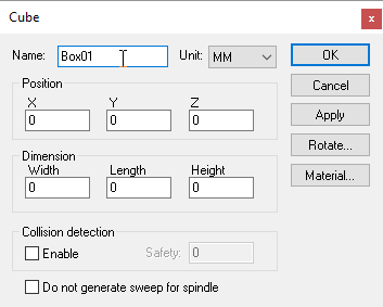
Creates a cubic (i.e., box) entity, given an XYZ origin and the width, length and height of the cube. Once created, the cube can be further rotated to its required orientation. Parameters common to all entities (not listed below) can be found here.
Width: The X axis width of the cube.
Length: The Y axis length of the cube.
Height: The Z axis height of the cube
Simulation»
Simulation»
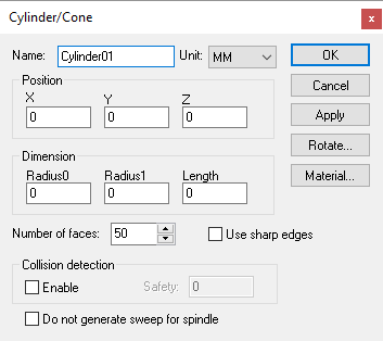
Creates a cylindrical or conical entity, given an XYZ origin and the radius and height of the cylinder. Once created, the cylinder can be further rotated to its required orientation. The starting and ending radii can also be modified. Parameters common to all entities (not listed below) can be found here.
Radius0: The radius of the cylinder or cone at the initial position.
Radius1: The radius of the cylinder or cone at the “length” height.
Length: The height of the cylinder or cone in the Z axis (use the Rotate button to orient the cone as required).
Simulation»
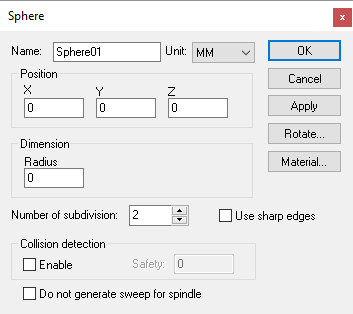
Creates a spherical entity, given an XYZ origin and the radius of the sphere. Once created, the sphere can be further rotated to its required orientation. The radius can also be modified. Parameters common to all entities (not listed below) can be found here.
Radius: The radius of the sphere.
Number of subdivisions: Controls the smoothness of the sphere. A value of 0 produces a (20 face) icosahedron, and increasing the subdivision value increases the faces by a factor of 3. A maximum of 6 subdivisions is permitted (very CPU intensive).
Simulation»
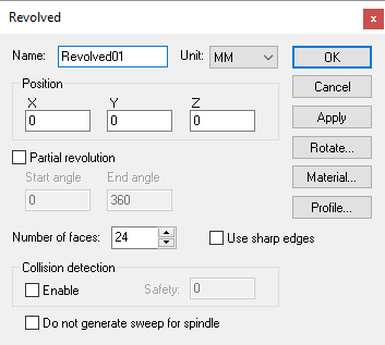
Sweeps a 2D profile over a complete or partial arc to produce a surface of revolution. Once created, the surface can be further rotated to its required orientation using the Rotate button. Parameters common to all entities (not listed below) can be found here.
Partial revolution: If selected the profile will be rotated between the Start angle and End angle positions. When not selected, a complete 360° arc is used.
Profile button: Select this button to enter the surface profile. The profile is defined as a series of (radius, height) pairs of coordinates, one pair per line, which is swept around the Z-axis. The order in which points are defined is important; the outside surface of the profile is to the left of the curve defined by the points. The profile does not have to be closed (i.e., it does not have to start and end at the same point). Use the Apply button in the profile builder to see changes to the profile curve.
Simulation»
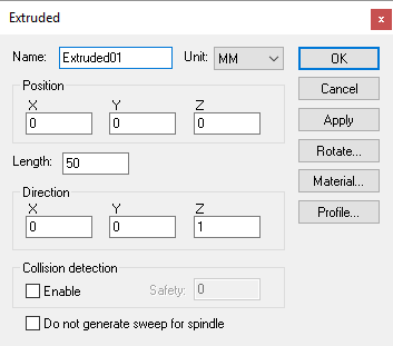
Sweeps a 2D closed profile along a vector to produce an extruded surface. Once created, the surface can be further rotated to its required orientation using the Rotate button. Parameters common to all entities (not listed below) can be found here.
Length: Specifies the distance to sweep the profile along the vector defined by the direction components.
Direction: Specifies the XYZ components of the vector to sweep the profile along.
Profile button: Select this button to enter the surface profile. The profile is defined as a series of (x, y) pairs of coordinates, one pair per line, which is extruded along a vector (positive Z by default) for the specified distance. The order in which points are defined is important; the outside surface of the profile is to the left of the curve defined by the points. The profile must be closed (i.e., it must start and end at the same point). You can specify one or more additional “island” contours to be subtracted from the main extruded shape by first specifying a semicolon contour separator followed by the series of (x, y) pairs of coordinates of the island contour, one pair per line. Use the Apply button in the profile builder to see changes to the profile curve.
Simulation»
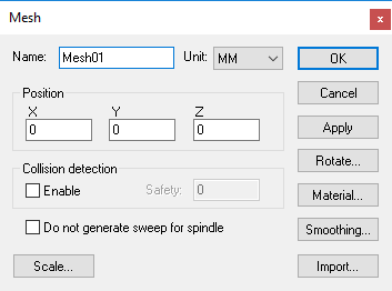
Imports an STL mesh into the model. Once imported, the mesh surface can be further rotated to its required orientation using the Rotate button. Parameters common to all entities (not listed below) can be found here.
Import button: Select this button to choose the STL file to be imported. An STL file does not define its units of measure; use the Units field on the STL import dialog to specify the dimensional units of the file. The import dialog also provides a File format field to specify the STL file format. Normally the default Auto selection should suffice; but if you have difficulty importing an STL file, try selecting other file formats. An STL file can be dragged and dropped onto the Import dialog.
Smoothing: Select this button to improve the appearance of facetted surfaces by using smooth light rendering at edges having a change of angle within a specified amount.
Scale button: Use this button to scale the STL mesh object if the object as imported is the wrong size. Alternately, you could import the object again this time specifying different dimensional units.
Simulation»
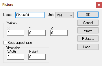
Loads a bitmap image, given the point in the model for the lower left corner of the image, and the X-axis width and Y-axis height of the image in model coordinates. The picture can be rotated to its required orientation using the Rotate button. Parameters common to all entities (not listed below) can be found here.
Width: Specifies the length of the image measured along the X-axis.
Height: Specifies the length of the image measured along the Y-axis.
Keep aspect ratio: If checked, the image will retain its original shape, which may result in the length or height being smaller than intended. Clear this checkbox to stretch the image into the space defined.
Load button: Select this button to choose the bitmap image (.bmp) to load into the model.
Bitmap images must be compatible for OpenGL graphic texturing, and therefore they have some important restrictions. Also note that Textures can place a heavy CPU burden on the rendering (image drawing) process, and can take up a lot of space in the Icam database.
Bitmaps must be constructed in 16-color or 256-color mode.
Bitmaps must not use RLE compression (i.e., they must be uncompressed).
The length and height of the image must be evenly divisible by a power of two.
Collision testing is not performed on picture entities.