Fixture, Part and Stock Functions
These functions provide tools for managing fixtures, parts, and stock within the simulation environment. They enable dynamic creation, modification, and transfer of simulation objects, as well as stock cleanup and export operations.
The $FMSCHIP Function
|
Remove unconnected stock fragments Returns: Numeric |


![\icamhsp{0.707mm}\bigl[,\mathit{id}\,\bigr]\icamhsp{0.707mm}\textbf{)}](../../_images/math/68d0106acdfa1a2c50cfa3dd7078304c05de7aed.svg)
The $FMSCHIP function is used to remove unconnected stock fragments using one of two available methods:
- DESIGN:
Remove any unconnected stock fragment that does not intersect the design part.
- VOLUME:
Remove any stock fragment that has a volume less than vol expressed in cubic model units (see the $UNISIM variable).
By default, chips are removed from all stock objects currently loaded in the simulation. Optionally, the id parameter can be used to restrict chip removal to a specific stock whose component ID is specified (see the $FMSID function). This function returns the number of chips that were removed.
The $FMSESF Function
|
Export the in-process stock Returns: Numeric |

![\icamhsp{0.707mm}\bigl[\,\mathit{id}\,\bigr]](../../_images/math/04c7be67019a41f96c1256e23fddb51fc34c8b1e.svg)
![\icamhsp{0.707mm}\raise0.03ex\hbox{$\Bigl[,\mathtt{\char39}\mathit{filepath}\,\mathtt{\char39}\,\bigl[,\mathtt{\char39}\mathit{filename}\,\mathtt{\char39}\,\bigr]\,\Bigr]$}\icamhsp{0.707mm}\textbf{)}](../../_images/math/bb6ec3d299ca80f16420119a75f6f96a4f3809d6.svg)
The $FMSESF function is used to export the in-process stock to an ASCII STL file.
If a stock component id is omitted, then all in-process stock is output to a single file, in the same directory and with the same file name as the GENER tape file or CERUN listing file, with a file type of “.stl”.
If a stock component id is given, then the specified stock object is output to a single file, named after the component itself with a file type of “.stl”, in the same directory as the GENER tape file or CERUN listing file.
The output file location and name can be changed by specifying a different filepath, or both a filepath and a filename. A relative filepath is with respect to the default output directory.
Specifying 0 (zero) for id is a special case, causing all stock objects to be output, but each to their own file, named after the stock object itself (the optional filename parameter is ignored in this case).
For example, the following macro code will output all stock attached to stock axis #1:
Q=$FMSID(PART,1,2,ALL)
DO/I=1,$FLEN(Q)
   OK=$FMSESF(Q(I))
ENDOF/DO
The $FMSFIXTURE Function
|
Fixture definition Returns: Numeric |

There are two forms of the $FMSFIXTURE function. CLEAR clears all or the specified fixture definition from the simulation. START-END creates new fixture definitions to be added to the simulation.
Clear fixture definitions
This form of the $FMSFIXTURE function removes all or the specified fixture definition from the simulation. To remove a specific fixture definition, identify it by its name or object ID. A value of 1 is returned if Virtual Machine is active, otherwise 0 is returned.
Create new fixture
This form of the $FMSFIXTURE function provides the ability to create a new fixture. To create a fixture, first call $FMSFIXTURE(START,name) where name is a string constant or variable defining the fixture name. Specify an optional stockaxis parameter to identify the stock-axis ID on which the fixture is attached (default none). A value of 1 is returned if Virtual Machine is active, otherwise 0 is returned.
Next, call $FMSFIXTURE(property,parameter-list) once for each fixture object and property to be defined, where the property name is specified using a string constant or variable containing the case-insensitive name of the property. A value of 1 is returned if Virtual Machine is active, otherwise 0 is returned. Available properties and their parameter values are listed below.
Properties defining objects:
A fixture can contain zero or more of each of the following object types:
Specifies a rectangular object, defined by: its string name; the xyz coordinates of one corner; and signed width (along x), length (along y) and height (along z) distances to the opposite corner.
Specifies a cylindrical or conical object, defined by: its string name; the xyz center coordinates and r1 radius of the one end; the r2 radius and height (along z) of the other end; the number of external faces (default 50) to use to approximate the curved surface; and a sharp flag value where 1 renders the cylinder with sharp edges and 0 (default) renders it with smooth edges.
Specifies a spherical object, defined by: its string name; the xyz center coordinates and r radius of the sphere; a subdiv “number of subdivisions” value (default 2) that controls the smoothness of the sphere with 0 producing a 20 face icosahedron and increasing subdivision values (to a maximum of 6) increasing the faces by a factor of 3; and a sharp flag value where 1 renders the sphere with sharp edges and 0 (default) renders it with smooth edges.
Specifies a mesh object, defined by: its string name; the string filename (relative to the current working directory) specifying the ASCII STL file containing the mesh geometry; the xyz origin of the mesh; a scale factor (default 1.0) to apply to the mesh; and a smoothing angle in degrees (default 0.0) that when positive will smoothly render edges that have a deviation no larger than the specified angle.
Object properties:
The following properties are modal and apply to subsequent object definitions:
Specifies the machinability property of the objects that follow. A flag value of 0 (default) indicates non-machinable objects. A value 1 indicates machinable objects for which material removal simulation is required. Any other positive value indicates machinable objects for which material removal simulation is not required.
Specifies the units of measure for subsequent objects (1:inch, 25.4:mm). Default units are the current machine units.
Specifies the position and orientation of subsequent objects using a 12 element matrix sequence.
Specifies the color of subsequent objects. The string colorname must have previously been defined using the $FMSCOLR function. A standard default grey color is used if one is not defined.
Lastly, call $FMSFIXTURE(END) to complete the fixture definition. The fixture object ID is returned if a dynamic fixture was created, otherwise 0 is returned.


![\icamhsp{0.707mm}\bigl[,\mathit{stockaxis}\,\bigr]\icamhsp{0.707mm}\textbf{)}](../../_images/math/3a59758482504992db971ff1d18fb55e7499495a.svg)


The $FMSPART Function
|
Part definition Returns: Numeric |

There are two forms of the $FMSPART function. CLEAR clears all or the specified part definition from the simulation. START-END creates new part definitions to be added to the simulation.
Clear part definitions
This form of the $FMSPART function removes all or the specified part definition from the simulation. To remove a specific part definition, identify it by its name or object ID. A value of 1 is returned if Virtual Machine is active, otherwise 0 is returned.
Create new part
This form of the $FMSPART function provides the ability to create a new part. To create a part, first call $FMSPART(START,name) where name is a string constant or variable defining the part name. Specify an optional stockaxis parameter to identify the stock-axis ID on which the part is attached (default none). A value of 1 is returned if Virtual Machine is active, otherwise 0 is returned.
Next, call $FMSPART(property,parameter-list) once for each part object and property to be defined, where the property name is specified using a string constant or variable containing the case-insensitive name of the property. A value of 1 is returned if Virtual Machine is active, otherwise 0 is returned. Available properties and their parameter values are listed below.
Properties defining objects:
A typical part consists of two objects: the in-process stock object and the design object. A part can contain zero or more of each of the following object types:
Specifies a rectangular object, defined by: its string name; the xyz coordinates of one corner; and signed width (along x), length (along y) and height (along z) distances to the opposite corner.
Specifies a cylindrical or conical object, defined by: its string name; the xyz center coordinates and r1 radius of the one end; the r2 radius and height (along z) of the other end; the number of external faces (default 50) to use to approximate the curved surface; and a sharp flag value where 1 renders the cylinder with sharp edges and 0 (default) renders it with smooth edges.
Specifies a spherical object, defined by: its string name; the xyz center coordinates and r radius of the sphere; a subdiv “number of subdivisions” value (default 2) that controls the smoothness of the sphere with 0 producing a 20 face icosahedron and increasing subdivision values (to a maximum of 6) increasing the faces by a factor of 3; and a sharp flag value where 1 renders the sphere with sharp edges and 0 (default) renders it with smooth edges.
Specifies a mesh object, defined by: its string name; the string filename (relative to the current working directory) specifying the ASCII STL file containing the mesh geometry; the xyz origin of the mesh; a scale factor (default 1.0) to apply to the mesh; and a smoothing angle in degrees (default 0.0) that when positive will smoothly render edges that have a deviation no larger than the specified angle.
Object properties:
The following properties are modal and apply to subsequent object definitions:
Specifies that subsequent object definitions define in-process stock objects. This is the default if neither STOCK or DESIGN is specified.
Specifies that subsequent object definitions define as-designed part objects.
Specifies the units of measure for subsequent objects (1:inch, 25.4:mm). Default units are the current machine units.
Specifies the position and orientation of subsequent objects using a 12 element matrix sequence.
Specifies the color of subsequent objects. The string colorname must have previously been defined using the $FMSCOLR function. A standard default grey color is used if one is not defined.
Lastly, call $FMSPART(END) to complete the part definition. The part object ID is returned if a dynamic part was created, otherwise 0 is returned.


The $FMSSETUP Function
|
Selection of setup number Returns: Numeric |
![\textbf{{\char36}FMSSETUP}\textbf{(}\icamhsp{0.707mm}\bigl[\,\mathit{n}\,\bigr]\icamhsp{0.707mm}\textbf{)}](../../_images/math/db2a3e252009a7426370f675c3aad07bd94cbada.svg)
The $FMSSETUP function selects the specified setup number n, as defined in the Simulation»
Manager “Setups” tree control. If the setup number n is omitted, the next sequential setup will be loaded. If the setup does not exist, the function returns with the value 0 (zero) and no change in setup occurs.
The $FMSTRN Function
|
Transfers part, stock or fixture components Returns: Numeric (always returns 1) |


![\icamhsp{0.707mm}\bigl[,\mathit{space\text{-}type}\,\bigr]\icamhsp{0.707mm}\textbf{)}](../../_images/math/87693e80165471a9a09e2e518b9e2ca79c06b6fd.svg)
The $FMSTRN function transfers part, stock or fixture components from the stock axis identified by from-id to the stock axis identified by to-id.
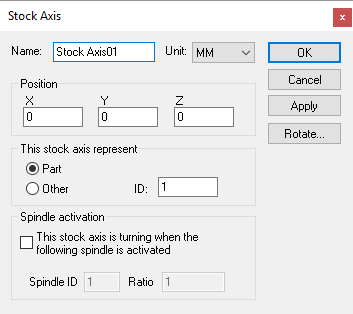
Only “part” stock axes can be specified as the source and target locations of a part transfer. The ID number is as defined in the Stock Axis dialog when creating the stock axis.
The space-type flag defines how the stock is moved, as follows:
- 0:
Local space (default): Object's relationship to to-id will be the same as the object's original relationship to from-id. Object typically will move.
- 1:
Global space: Object will be transferred from from-id to to-id without physically moving.