Toolbars provide quick and easy access to the most commonly used
controls. Toolbars can be activated or hidden using the Tools»Toolbar
menu selection, which opens the Toolbars dialog. With GENER and CERUN,
toolbars can also be activated or hidden using a right-mouse context
menu from the application window background. Toolbars are dockable,
meaning that you can drag a toolbar to any of the four sides of the main
window. Toolbars can also be undocked by dragging them away from the
sides (or by holding the Ctrl key). This section describes the Virtual
Machine toolbars and their associated functions and short-cut keys.
Not all toolbars and toolbar functions are available in all products. If
a toolbar is not universally available, the applicable products are
listed in the title.
View (CERUN & GENER only)
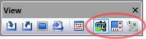
The View toolbar is one of the standard toolbars available with the
GENER and CERUN UI. This toolbar has buttons that control the visibility
of windows used to trace the inputs and outputs of the process. Three of
these buttons are unique to VM, as follows:

Simulation»Virtual Machine: Views or hides the simulation
windows.

Simulation»Controller: Views or hides the Controller
window, which is used to jog axes, set tool and fixture compensation,
and to replay the simulation at any point in time.

Simulation»Manager: Views or hides the Simulation Manager
window, which is used to view or modify tooling, parts, fixtures and
setups.
VM Construct (QUEST only)
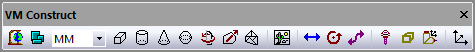

Simulation»Use World CS: When selected, object
coordinates are listed in world coordinates, originating from the center
of the grids. When unselected, an object’s coordinates are listed
relative to its parent (i.e., in local coordinates). This button also
affects the placement of objects copied from one place to another in the
model navigator. When world coordinates are selected, the object retains
its position despite being moved or copied from one place to another in
the navigator hierarchy. When local coordinates are selected, the object
is placed relative to its new parent at the same offset it was
originally at relative to its old parent.

Simulation»Group Selection: When selected, picking any
component of a group will select the entire group. Objects can be
grouped into larger components, for selection purposes, in the
3D Models»Groups»Selection section of the model navigator.

Simulation»Construct Entity»Cube: Creates a cubic entity,
given an XYZ origin and the width, length and height of the cube. Once
created, the cube can be further rotated to the required orientation.

Simulation»Construct Entity»Cylinder: Creates a
cylindrical entity, given an XYZ origin and the radius and height of the
cylinder. Once created, the cylinder can be further rotated to the
required orientation. The starting and ending radii can also be
modified.

Simulation»Construct Entity»Cone: Creates a conical
entity, given an XYZ origin, base radius and height of the cone. Once
created, the cone can be further rotated to the required orientation.
The starting and ending radii can also be modified.

Simulation»Construct Entity»Sphere: Creates a spherical
entity, given an XYZ origin and radius of the sphere. Once created, the
sphere can be further rotated to the required orientation. The “number
of subdivisions” controls the smoothness of the sphere, with a value 0
producing a (20 face) icosahedron, and increasing subdivisions increases
the faces by a factor of 3. A maximum of 6 subdivisions is permitted
(very CPU intensive).

Simulation»Construct Entity»Revolved: Sweeps a 2D profile
over a complete or partial arc to produce a surface of revolution. The
profile is defined as a series of (radius, height) pairs of coordinates,
which is swept around the Z-axis. Once created, the surface can be
further rotated to the required orientation.

Simulation»Construct Entity»Extruded: Sweeps a 2D closed
profile along a vector to produce an extruded surface. The profile is
defined as a series of (x, y) pairs of coordinates, joined at the start
an end, which is extruded along a vector (positive Z by default) for a
specified distance. Once created, the surface can be further rotated to
the required orientation.

Simulation»Construct Entity»Mesh: Imports an STL mesh
into the model. Once imported, the mesh surface can be further scaled
and rotated to its required size and orientation. A “Smoothing” function
can improve the appearance of facetted surfaces by using smooth light
rendering at edges having a change of angle within a specified amount.

Simulation»Construct Entity Picture: Loads a bitmap
image, given the point in the model for the lower left corner of the
image, and the X-axis width and Y-axis height of the image in model
coordinates. The picture can be rotated to the required orientation.

Simulation»Construct Axis»Linear Axis: Creates a linear
axis, given a point of origin and the direction and range of motion.

Simulation»Construct Axis»Rotary Axis: Creates a rotary
axis, given a point of origin, the rotation axis and an optional range
of motion.

Simulation»Construct Axis»Curve Axis: Creates a curved
axis, given a point of origin and an open or closed 2D profile. The
profile is defined as a series of (x, y) pairs of coordinates. The
curved axis can be further rotated the required orientation.

Simulation»Construct Axis»Tool Axis: Creates a tool
reference point that can identify one of: the SCP of the machine, a
specific pocket in the tool changer, or other named places where tools
might be attached.

Simulation»Construct Axis»Stock Axis: Creates a part
reference point that identifies where fixtures and parts are loaded on
the machine.

Simulation»Construct Axis»Head Axis: Creates a head
reference point that can identify one of: the head attachment point on
the machine, head storage locations for inactive heads, and other places
where heads might be attached.

Simulation»Construct Axis»Reference Axis: Creates a
reference point in the model. Reference points are used to group related
entities.
VM Mode (CERUN & GENER only)
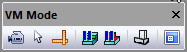

Simulation»Mode»Camera: Selects “camera” mode, which is
equivalent to selecting the “Default to camera mode” checkbox in the
Simulation»Options (Ctrl Alt O) Misc settings. The left-mouse button
will subsequently control the orientation of the camera. The mouse
pointer will appear as a four-way arrow. Hold the Ctrl key down to
temporarily (while the key is held) switch to “selection” mode.

Simulation»Mode»Selection: Selects “selection” mode,
which is equivalent to clearing the “Default to camera mode” checkbox in
the Simulation»Options (Ctrl Alt O) Misc settings. The left-mouse button
will subsequently select objects. The mouse pointer will appear as an
arrow. Hold the Ctrl key down to temporarily (while the key is held)
switch to “camera” mode.

Simulation»Mode»Measurement: Selects “measurement” mode.
The left-mouse button will subsequently select objects for measurement
purposes. The mouse pointer will appear as caliper/square combination.
Hold the Ctrl key down to temporarily (while the key is held) switch to
“camera” mode.

Simulation»Mode»Pause Material Removal: Temporarily
disables material removal simulation (MRS). When selected, the
in-process stock and machinable fixtures will not be affected by the
cutting action of the tool.

Simulation»Mode»Pause Gouge Detection: Temporarily
disables tool vs. part gouge detection. When selected, interference
(i.e., collisions) will no longer be diagnosed between the cutting tool
and the design part.

Simulation»Show»Wireframe: Switches between wireframe
and solid rendering of objects in the Simulation window.

Simulation»Show»Display: Views or hides the heads-up
status display that floats above the simulation window. The HUD is not
available with QUEST.
VM Grid
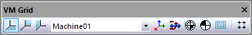
The VM Grid toolbar contains a drop-down list of all axes defined in the
model (including tool, head and stock axes). The grid reference zero and
orientation will be with respect to the selected axis. The standard
viewpoint settings in the VM View toolbar are also with respect to the
selected grid axis.

Simulation»Show»XY Plane Grid: Views or hides the XY
plane grid. Line spacing, colors, units and other settings are
controlled by selecting Simulation»Grid (Ctrl G).

Simulation»Show»YZ Plane Grid: Views or hides the YZ
plane grid.

Simulation»Show»ZX Plane Grid: Views or hides the ZX
plane grid.

Simulation»Show»Axes Marker: Views or hides the axes
marker showing the origin. Marker size, colors and other settings are
controlled by selecting Simulation»Grid (Ctrl G).

Simulation»Show»Kinematics: Views or hides the kinematics
markers showing the type and position of linear axes, rotary axes, and
the TCP and SCP control point positions.

Simulation»Show»Safety Zones: Views or hides the display
of the safety zone that surrounds objects that have a safe distance
setting for collision testing. The safety zone is drawn with a fixed
transparent color, so that the underlying object can also be seen.

Simulation»Show»Workpiece Reference: Views or hides the
display of a marker showing the origin and orientation of the workpiece
coordinate frame. This frame includes the effects of fixture
compensation, RTCP and any local coordinate system (LCS).

Simulation»Show»Tool Reference: Views or hides the
display of a marker showing the offset at the spindle control point
(SCP) due to the effects of tool length or tool offset compensation.

Simulation»Grid (Ctrl Alt G): Enables or disables the
“snap-to-grid” mode of object construction using the mouse. When
enabled, mouse coordinates snap to a defined grid size. Hold the Shift
key to temporarily (while the key is held) reverse the snap-to-grid
setting. Grid spacing can also be set by selecting Simulation»Grid.
VM View
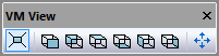
The 6 middle buttons on the VM View toolbar lock the simulation window
camera rotation to one of 6 standard views, with respect to the axis
selected in the VM Grid toolbar. While any one of these 6 buttons is
selected, camera rotation functions are disabled and the camera can be
panned only.

Simulation»Camera»Perspective: Switches to a 3D
Perspective view of the simulation window. When deselected, switches to
an Orthogonal view of the simulation window.

Simulation»Camera»Front: Switches to a front view of the
simulation window.

Simulation»Camera»Back: Switches to a back view of the
simulation window.

Simulation»Camera»Top: Switches to a top view of the
simulation window.

Simulation»Camera»Bottom: Switches to a bottom view of
the simulation window.

Simulation»Camera»Left: Switches to a left side view of
the simulation window.

Simulation»Camera»Right: Switches to a right side view of
the simulation window.

Simulation»Camera»Fit: Fits the selected object(s) in the
simulation window view.
VM View Filter (CERUN & GENER only)
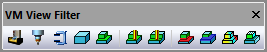

Simulation»Show»Filters»Machine: Views or hides the
display of the machine model and any head components.

Simulation»Show»Filters»Tools: Views or hides the display
of the tools.

Simulation»Show»Filters»Fixtures: Views or hides the
display of the fixtures.

Simulation»Show»Filters»Stock: Views or hides the display
of the initial stock.

Simulation»Show»Filters»Parts: Views or hides the display
of the finished parts.

Simulation»Show»Filters»In-process Stock: Views or hides
the display of the in-process stock, as calculated by the Material
Removal Simulation option.

Simulation»Show»Filters»Stock Checkpoints: Toggles the
display of the in-process stock as it appeared at earlier moments in
time when moving the Time Line backwards and forwards. These earlier
checkpoints can be taken at each tool change, at each operation and/or
periodically during long cutting sequences as controlled from the
Simulation»Options menu MRS tab “In-process stock checkpoints” settings.

Simulation»Show»Filters»Boolean Overcut: Views or hides
the display of gouges in the finished part, as calculated by the
Material Removal Simulation option.

Simulation»Show»Filters»Boolean Undercut: Views or hides
the display of excess stock material, as calculated by the Material
Removal Simulation option.

Simulation»Show»Filters»Colorized Boolean: Views or hides
the display of a color graduated difference between stock and part, as
calculated by the Material Removal Simulation option. Select
Simulation»Compare (Ctrl Alt Q) to view or modify comparison settings.
Colorized differences are available only when one or both of the Overcut
or Undercut buttons are selected.

Simulation»Show»Filters»Transparent Zero: Modifies the
display of colorized differences between stock and part to either show
in a transparent color, or not show, all faces of the gouge or excess
material that are within an acceptable tolerance with respect to the
part.
VM Measure
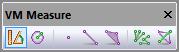
The buttons on the VM Measure toolbar are only available while in
measurement mode, as set using the Measurement button on the
VM Mode toolbar or Simulation»Mode»Measurement menu bar. The 3 middle
buttons are filters that enable or disable picking of the various
components of the triangles that make up the in-process stock.

Simulation»Measure»Distances and angles: Measures the
distance and angle between subsequently selected entities, as well as
the xyz offset between entities.

Simulation»Measure»Radius and center: Measures the radius
and xyz center of a circle constructed through 3 subsequently selected
points and/or edge midpoints.

Simulation»Measure»Vertex: Enables or disables the
picking of points on the boundary of the triangles that make up the
object.

Simulation»Measure»Edge: Enables or disables the picking
of edges of the triangles that make up the object.

Simulation»Measure»Face: Enables or disables the picking
of faces of the triangles that make up the object.

Simulation»Measure»Fan: Switches between chained (one to
the next) and fanned (one to many) measurements.

Simulation»Measure»Overlay: When enabled, the objects
selected for measurement will always be visible, no matter how the
camera is oriented.
VM Cross Section (CERUN & GENER only)
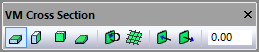
The Cross Section functions can be used to obtain a cross section view
of the in-process stock, which is only available when the Material
Removal Simulation (MRS) license option is enabled.

Simulation»Show»Cross Section»XY Plane: Enables or
disables a cross section view of the in-process stock taken along the XY
plane of the stock axis. The section plane can be offset by entering a
value in the numeric input field.

Simulation»Show»Cross Section»YZ Plane: Enables or
disables a cross section view of the in-process stock taken along the YZ
plane of the stock axis. The section plane can be offset by entering a
value in the numeric input field.

Simulation»Show»Cross Section»ZX Plane: Enables or
disables a cross section view of the in-process stock taken along the ZX
plane of the stock axis. The section plane can be offset by entering a
value in the numeric input field.

Simulation»Show»Cross Section»Custom Plane: Enables or
disables a cross section view of the in-process stock taken along a
plane defined using the Simulation»Measure picking functions. The
section plane can be offset by entering a value in the numeric input
field.

Simulation»Show»Cross Section»Invert Plane: Switches
between showing the in-process stock on one side of the cross section
plane or the other.

Simulation»Show»Cross Section»Show Grid: Enables or
disables the display of a grid on the cross section plane. Grid settings
are the same as for the Simulation»Grid feature.

Simulation»Show»Cross Section»Push Plane: Each press of
this button further offsets the cross section plane by a fixed amount
(as defined in the Simulation»Options dialog Misc tab) towards the
visible portion of the in-process stock. The current offset is shown in
the numeric field.

Simulation»Show»Cross Section»Pull Plane: Each press of
this button further offsets the cross section plane by a fixed amount
(as defined in the Simulation»Options dialog Misc tab) away from the
visible portion of the in-process stock. The current offset is shown in
the numeric field.
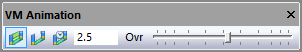
VM Annotation (CERUN & GENER only)
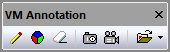
The Annotation functions provide a rudimentary capability to first
(optionally) mark-up the simulation window and then take snapshots
and/or videos of the simulation.

Simulation»Annotation»Annotate: Toggles the left-mouse
action between annotate and non-annotate modes. When in annotation mode,
the cursor will appear as a small pencil that will draw in the
simulation window when the left-mouse button is held down. Drawing is
equivalent to marking a glass pane that appears on top of the simulation
window.

Simulation»Annotation»Color: Opens a dialog that selects
the drawing color.

Simulation»Annotation»Erase: Clears the drawing pane
(this cannot be undone).

Simulation»Annotation»Snapshot: Takes a PNG image of the
simulation window, including annotation data if present. Picture files
are stored in the folder identified by the vm_picture_dir configuration
(i.e., DEF file) variable. If this variable is not defined or is blank,
then pictures are stored in the user’s “Pictures\ICAM\270” folder.
Picture files are named “picnnn.png”, where nnn is a number
automatically chosen to avoid overwriting an existing picture.

Simulation»Annotation»Record: Starts or stops the
recording of the contents of the simulation window, including annotation
data if present. Video files are stored in the folder identified by the
vm_video_dir configuration variable. If this variable is not defined or
is blank, then videos are stored in the user’s “Videos\ICAM\270”
folder. Video files are named “videonnn.avi” where nnn is a number
automatically chosen to avoid overwriting an existing video. Recording
options can be set by selecting the Video button in the
Simulation»Options dialog Misc tab.

Simulation»Annotation»Open: This provides quick and easy
access to the user’s pictures and videos folders.