Setting Tool Compensation
Most CNC’s provides some form of tool compensation to adjust
for differences in the length (or position) and diameter of the tool.
Advanced controllers provide 3D compensation, which can also compensate
for differences in tool corner radius. VM provides a virtual controller
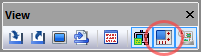
that supports these forms of tool compensation. The Controller window
can be toggled from the View toolbar by selecting the button shown
circled in the toolbar above, or by selecting Simulation»
Icam provides “Manufacturing Extractors” for many popular CAM systems, which can automatically define tool compensation settings from tooling used in the NC program.
Tool compensation data is automatically saved in the verification setup (.vsw) file when the program ends. This setup file will be reused on subsequent runs to reestablish the tool compensation settings necessary for an accurate simulation.
Length Compensation
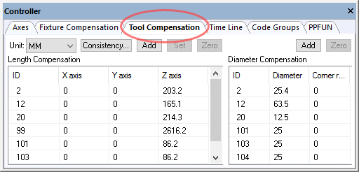
Length compensation typically adjusts the Z-axis position of the control point, to account for differences between programmed and actual tool lengths. If the NC program already compensates for tool lengths in the coordinate data, then length compensation is not necessary in VM. If the coordinate data does not take into account the gauge length of the tool, then length compensation must be used with VM to correctly check the NC program. Press the Add button and then enter the length compensation ID to be added. You can select any axis of any ID and type a new value. You can also select one or more IDs and use the Set and Zero buttons to set or zero offsets for all selected IDs simultaneously. Select the Consistency button to compare the tool length settings defined for each tool against their corresponding tool length compensation amounts. Inconsistencies are listed along with the choice to correct problems for all, selected or no tools.
Diameter Compensation
Diameter compensation adjusts the trajectory of the tool to compensate for differences between the programmed and actual tool diameters, or tool shapes. Most CAM systems output coordinate data that is already offset from the part surface by the radius of the tool, making diameter compensation unnecessary in VM. If the coordinate data represents the contact point of the tool with the surface instead of the tool center point, diameter compensation must be used with VM to correctly check the NC program. Press the Add button and enter the diameter compensation ID to be added. Then select the ID and enter the diameter and corner radius. You can also select one or more IDs and use the Zero button to zero offsets for all selected IDs simultaneously.