Creating a Virtual Machine Model
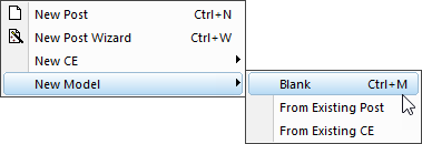
You create a new model using the
File»
Regardless of how the model is created, the Main work window will then change to show a short list of questions.
General Information
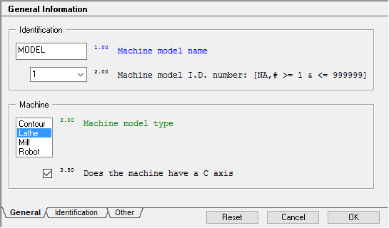
Your first action should be to give the new model a unique
name. This is the name that you will later use with GENER and CERUN to
identify the machine model (see “Selecting a Virtual Machine Model”).
The model name and model ID number follow the exact same naming
convention as that used for Icam post-processors and control emulators
(i.e., alphabetic first character, up to 31 additional alphabetic,
numeric and/or underscore “_” characters, followed by an optional ID
number in the range 1-999999). The model name/ID combination must not
conflict with a post-processor or control emulator name/
Next, choose the type of machine from the list of selected types. VM supports contouring, milling, turning and robot type machines. The choice of contouring or milling machine type has no effect at all on the model. Selecting a lathe machine type will activate additional features in VM to handle lathe turrets, live tooling and spindles that can switch between turning and cutting modes. Selecting a robot machine type requires that 6 rotary joints be later defined in the model.
The model units system defines the default unit of measure to be used when constructing components. It need not match the units of the post-processor or control emulator. You should select the same unit system that is used in the drawings and diagrams of your machine.
Note
You should not change the model units once you have already started building the model. This is because the model dimensions will be reinterpreted using the new units value, resulting in a scaling of the model. If you really must change the model units, then follow these steps: 1) Use the model navigator to select the entire model and cut it into the paste buffer. 2) Change the model units. 3) Use the model navigator to paste the contents of the buffer back.
3D Models»
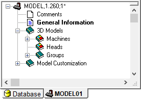
Next, you should open the “Machines” entry in the Model Navigator window (as shown at right). Either double-click on the Machines entry, or right-mouse click on the entry and select Open from the pop-up context menu. In either case, a view of the model world, with a default grid (and default lighting) will appear in the upper right work area.
You should now adjust the grid size so that it can comfortably contain
the footprint of the machine model. Select Simulation»
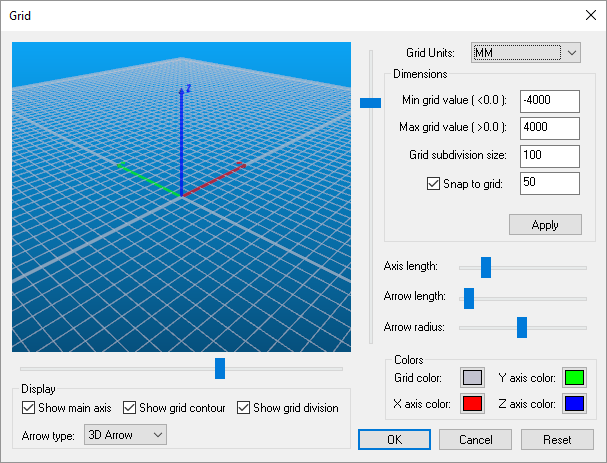
A moderately oversized grid generally provides a pleasing visual effect. Do not use an undersized grid, since this will adversely affect image rendering. The grid size is defined by minimum and maximum values, which are applied to the world X and Y axes. The grid zero point is also the default model zero point. The grid subdivision size is for visual effect only (it gives the floor some substance) but be aware that too fine a grid will slow down the rendering speed. The snap-to-grid setting can be of some aid during interactive creation of components.
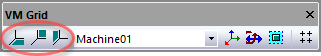
Grid visibility can be controlled either from the buttons
shown circled on the VM Grid toolbar at left, or from the
Simulation»
The origin of the grid is the point around which the camera will rotate
by default, unless another object is selected as the camera pivot point
using Simulation»
Grid settings are stored with the model in the database.
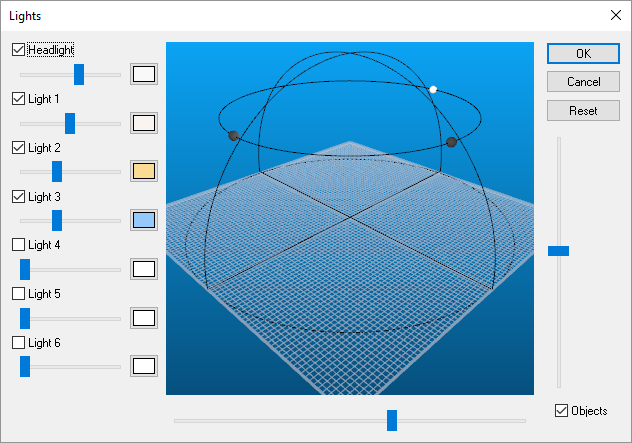
You should next reset the default lighting to respect the new grid size.
Select Simulation»
Select the Reset button to setup a default lighting scheme to match the grid size. You should wait until your machine begins taking shape before further adjusting the lighting.
Light settings are stored with the model in the database. When the Reset button is used in QUEST, the lighting resets to the default 4-light configuration (headlight plus 3 movable lights) shown below. When the Reset button is used in GENER and CERUN, the lighting will reset to the settings stored with the model.
Comments
The Comments section provides a rudimentary Notepad style editor that can be used for your own purposes. Anything you type in this section will be saved with the model. It is recommended that updates to the model be documented in the Comments section. This will help in later identifying different revisions of a model in the database.