Overview
The Icam Virtual Machine (VM) simulator graphically depicts the operation and motions of a CNC machine during post-processing and MCD simulation.
VM is integrated with Icam Post GENER (the post-processor), which uses the virtual CNC machine model to detect collisions and overtravel conditions. Collision detection can account for the effects of work piece and tool compensation, given experimental or actual values for compensation offsets. Collision detection is a natural part of the look-ahead optimizations that GENER performs during path planning, meaning that GENER can automatically choose an appropriate tool path to avoid collisions where possible. The machine simulation can be displayed in one of the GENER output windows, synchronized with other GENER output. Collision detection and avoidance can be active even when the simulation is not being show, for example, when running GENER in a minimized state.
VM is also integrated with CERUN (the control emulator), which uses the virtual CNC machine model to detect and report collisions and overtravel conditions during MCD based machine simulation. As with GENER, collision detection with CERUN can account for the effects of work piece and tool compensation, given experimental or actual values for compensation offsets. The machine simulation can be displayed in one of the CERUN output windows, synchronized with other CERUN output. Collision detection can be active even when the simulation is not being show.
A complete machine simulation requires the following:
A computerized model of the machine
A post-processor or control emulator to drive the simulation
Cutting tool, holding fixture, finish part and rough stock definitions
Workpiece and tool compensation amounts
The CNC machine model is developed and maintained using the Icam QUEST Developer’s System. A model describes both the kinematics and the physical characteristics of the machine. Kinematics include at a minimum the linear and rotary axes of the machine, and if desired, other moving components such as tool changers, pallet indexers, flexible holding devices, doors and the like. The physical components of the machine can be created using rudimentary design features of QUEST, or can be imported as STL objects from any CAM system. The model designer can define standard viewpoints and lighting arrangements to best view the simulation. Models can also be customized using Icam’s Macro programming facility to match special requirements of the machine.
Post-processors and control emulators are developed and maintained using the same QUEST system used for models. When GENER (the post-processor) controls VM, model motions reflect the post-processor’s understanding of the state of the machine. When CERUN (the control emulator) controls VM, model motions reflect the state of the machine as defined by the MCD (machine control data) itself.
Models, post-processors and control emulators are all stored in a proprietary format in an Icam database (.dbf) file.
An accurate simulation involves more than just moving the machine through its paces. Cutting tools and tool compensation amounts, holding fixtures and workpiece compensation amounts, and rough stock and finished part definitions should all be present in order to produce a meaningful result. Once defined, this information is saved in a verification setup (.vsw) file named after the input file (i.e., the CLDATA file when running GENER; or the MCD file when running CERUN). This verification setup file can be reused on subsequent runs to quickly reestablish the conditions necessary for the simulation.
Cutting tool definitions can be automatically created from CUTTER commands in the CLDATA file, however the ISO standard 7-parameter cutter format limits tools defined this way to milling tools only. A tool creation facility exists within the VM run-time interface to define milling tools, lathe tool inserts, probe tools and hybrid additive manufacturing (AM) tools. Tool holders can also be defined, either as 2D revolved profiles or imported as STL objects, which can then be associated to individual tools.
Tooling information and associated length and diameter compensation amounts are saved in the verification setup file, which can be later imported at the start of the same or any other verification session. This is ideal for cases where standard tooling is in use at a machine. A tool creation Wizard is available to help extract tooling information from tooling data output in list format by other tooling systems.
Holding fixture definitions must be imported as STL objects or created using the rudimentary design features of VM. Components of the fixture can be identified as machinable or non- machinable, to handle cases where it is not an error to have contact between the cutting tool and portions of the fixture. By default, any contact of the machine or tool with the fixture will signal an error.
Finished part definitions must also be imported as STL objects or
created using the rudimentary design features of VM. Any contact of the
machine or tool with the part will signal an error. In order to avoid
false collision reports on finish cuts, VM only reports tool/
Rough stock definitions, if used, must also be imported as STL objects or created using the rudimentary design features of VM. When licensed for material removal simulation, VM uses the stock definition for in-process stock verification and collision testing purposes. If material removal simulation is not licensed or is not enabled, then VM simply displays the rough stock for information purposes only (the appearance of the stock model can prove helpful when viewing the simulation).
Fixture, part and stock information, along with workpiece compensation amounts are saved in the verification setup file, which can be later imported at the start of the same or any other verification session.
Icam provides a number of “Manufacturing Extractor” utilities that run with supported CAM systems. These utilities automatically extract all of the tool, stock, part, fixture and related compensation information from the CAM manufacturing process and save it as a “job file” to be used when simulating the process. Extractors are available for:
3DEXPERIENCE 2015x–2025x
CATIA V5R21, V5-6R2012–2025
Cimatron 2025
Creo 7-11
FeatureCAM 2017–2025
Fusion 360 2021-2025
GibbsCAM 2024–2026
Mastercam 2019–2025
NX12, 1847, 1872, 1899, 1926, 1953, 1980, 2007, 2206-2412
PowerMill 2021–2025
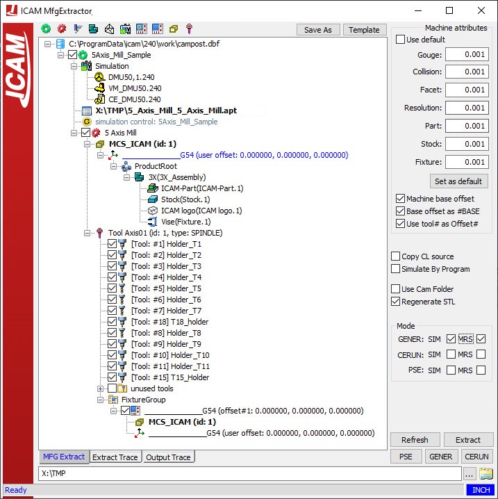
Extractors may have become available for other CAM systems since this document was published. For up to date information, see the “Kit Help” on-line help, available from the “Icam V27 x64” Start menu. A typical extractor is shown below.