Activating the Simulation Windows
GENER and CERUN must be started using the “Full” interface display
setting on the main launch panel in order to see the machine simulation
(this is equivalent to specifying the “/verbose” option on the command
line). Once the GENER or CERUN full user interface (UI) appears, the
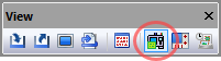
simulation windows can then be activated from the View toolbar by
selecting the button show circled in the toolbar above. Select the
button a second time to either hide the simulation windows or to restore
simulation windows that have been hidden. The simulation windows can
also be controlled by selecting Simulation»
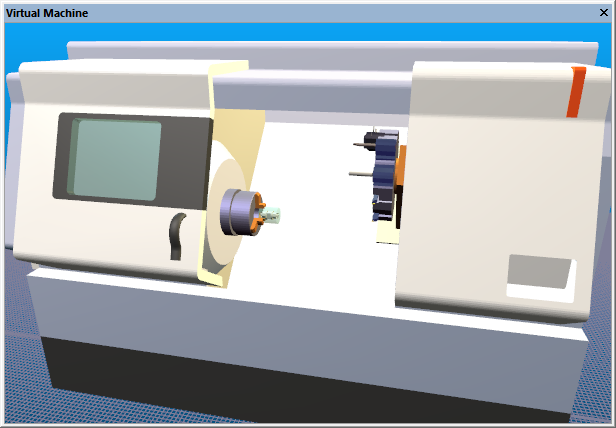
Simulation windows can display the machine model, tools and
their holders (and heads), fixtures and chucks, finished part and
corresponding rough stock. There are various Simulation»
Note
It is important to note that collision and overtravel detection (GENER and CERUN) and collision avoidance (GENER) are not affected in any way by the state of the simulation windows.
Pressing the right-mouse button in a simulation window will pop up a context-sensitive menu with various actions available depending on the object under the mouse pointer when the button was pressed, including the ability to view and in some cases change the object’s properties.
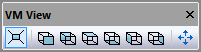
The VM View toolbar buttons let you toggle between perspective and orthographic projection, snap the camera to standard machine views (Front, Back, Top, etc.), and automatically fit either the selected object or the entire scene for optimal visibility. See Simulation»
Virtual Machine for details on using the mouse and keyboard to navigate and control the camera in the simulation window.
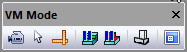
The VM Mode toolbar buttons control the selection mode (camera vs. select vs. measure), inhibit material removal simulation and tool vs. part collision testing, select wireframe vs. solid display of objects, and enable a “heads up display” that appears overlaid in the simulation window.
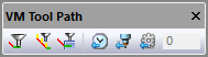
The VM Tool Path toolbar buttons enable the tracing of the tool-path and the tool-axis vectors in the simulation window, as well as the extent of the trace (showing the last n seconds, tools or operations).
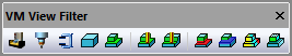
The VM View Filter toolbar buttons toggle the visibility of the machine, tooling, fixtures, initial stock, design part, in-process stock and stock checkpoints, gouged material and excess material.
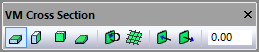
The VM Cross Section toolbar buttons section the in-process stock for better visibility and measurement purposes. The stock itself is not affected.
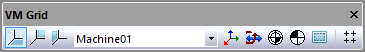
The VM Grid toolbar provides selectable datum-plane grids, coordinate frame references, various kinematics markers, a safety-zone visibility toggle and a snap-to-grid setting.