Simulation»
This menu bar selection provides the ability to add parts and fixtures to the simulation. This information is stored in a 3D model (.m3d) file, in the same directory and with the same name as the verification setup (.vsw) file. These two files are automatically saved when the program is completed. They will be reused on subsequent runs to quickly reestablish the material conditions necessary for an accurate simulation.
Parts can be composed of both a rough stock, used for material removal
simulation, and the design part, to which it can be compared using the
Simulation»
Part»
Design: The cutting portion of the tool can interfere (without diagnostics) with the design part, to the extent of the gouge tolerance. The gouge tolerance amount is defined in the Simulation» Options dialog Tolerances tab. Some gouging is to be expected, due to the effects of the manufacturing tolerance used by the CAM system when creating the tool path and the tolerance used in the creation of the STL part model. If CAM manufacturing and STL tolerances are not adjusted, the gouge tolerance should not have to be changed from one part to the next. The non-cutting portion of the tool, the tool holder and all other collision-enabled components of the machine are also tested for collision with the design part. The gouge tolerance is not applied when testing for part collision with these components.
Part»
Stock: With the Material Removal Simulation (MRS) license option enabled, VM can compute the in-process state of the raw stock. The path of the cutting portion of the tool will be “subtracted” from the stock during the manufacturing process in the same way that material is removed during real machining. Motions that cut the stock at rapid or while the spindle is stopped, will be diagnosed with an error. These cuts will also appear highlighted on the in-process stock object and identified as a collision in the Time Line display. Individual components of the stock can be enabled or disabled for MRS simulation using the component’s Material Removal column setting. If an MRS license is not available or not enabled, any object defined as stock is shown in the simulation windows but is ignored for collision testing purposes. To enable collision testing on a near-net stock shape, define it instead as machinable fixture. This will allow only the cutting portion of the tool to interfere with the stock provided that the motion is at feed and the spindle is turning.
Fixture: Individual components of a fixture can be identified as machinable or not, which affects how they are tested for collisions.
A machinable component might be a “soft” clamp or plate that will be cut by the tool during the manufacturing process. With the Material Removal Simulation (MRS) license option enabled, VM can optionally compute the in-process state of machinable fixture components, treating them as though they were defined as stock objects (see stock definition above).
If an MRS license is not available, or is not enabled for a machinable fixture component, then the cutting portion of the tool is not tested for collision with the fixture component if the tool is spinning and the cutting motion is at feed. The non-cutting portion of the tool, the tool holder and all other collision-enabled components of the machine are always tested for collision with machinable fixture components.
Non-machinable fixture components are always tested for collision against the entire tool, the tool holder and all other collision-enabled components of the machine.
VM does not check for interference between part and fixture, so they can partially or completely overlap each other without problems.
Collision testing is performed by sampling the motions of the machine
along the tool path. The rate of sampling, called the collision
tolerance, is defined in the Simulation»
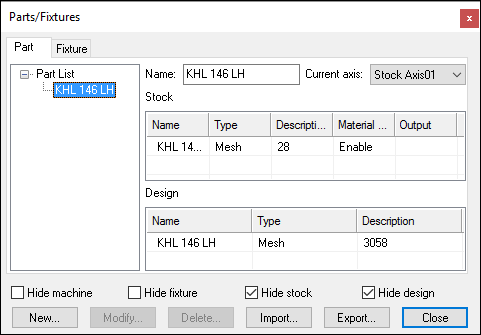
Objects are maintained in two lists, accessible by selecting one of the Part or Fixture tabs at the upper left corner of the dialog. For each type, a navigator along the left hand side of the dialog lists all of the objects defined for that specific type. For example, a fixture might consist of many parts, such as a base plate, clamps, spacers and so on. Select Import to bring in the part and fixture definitions from a different part program. Select Export to save the current part and fixture definitions to a named file for use in a different part program.
Select the top entry in the navigator to see list of objects for the selected type. Select New followed by New Part or New Fixture to create a new object. The object’s name is used by VM when reporting collision diagnostics. The object’s current axis defines the stock axis (or mounting point) where the object will be attached to the machine model at the start of the program. Machine models with multiple tables or pallets may define multiple stock axes. Click on an entry in the table to change the object’s name, its default axis (used when the program starts) or the current axis (the association in force at this point in the program). Setting the current axis value to “None” removes the part or fixture from the simulation, but not from the list of objects. You can select one or more objects in the right hand list and press the Delete button to completely remove them.
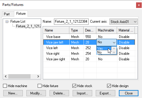
Each object can consist of one or more physical components, which are listed when you select an object name in the left hand list box, or when you select an object in the right hand object list and press the Modify button. Each component of an object can be given a name, which will be reported during collision diagnostics (e.g., “KHL 146 LH”). Fixture components can be tagged as machinable or not. Part components are never machinable; stock components are ignored for collision testing purposes.
Select the New button to add a new component. The following component types can be added:
Cube: Defines a cubic (i.e., box) entity given the XYX coordinates of one corner and the width, length and height (∆XYZ).
Cylinder: Defines a cylindrical or conical entity given an XYZ coordinate of the center, an initial radius, a final radius and the overall height. The surface of the cylinder is approximated by a number of faces, which can be specified. The light rendering at the edges between faces can be set smooth or sharp, allowing hexagon shapes to be defined.
Cone: Defines a conical entity given an XYZ coordinate of the center, an initial radius, a final radius and the overall height. The Cone and Cylinder definitions are identical; they differ during construction only.
Sphere: Defines a spherical entity given an XYZ coordinate of the center and a radius. The surface of the sphere is approximated by a number of faces, which can be controlled by the subdivision size (0 produces a 20 face icosahedron and each increase in subdivision value increases the faces by a factor of 3). The light rendering at the edges between faces can be set smooth or sharp.
Import STL: Imports an STL file relative to a specified XYZ location in the model. A “Smoothing” function can improve the appearance of faceted surfaces by using smooth light rendering at edges that have a change of angle within a specified amount.
Components are created interactively in the simulation window. The
various Hide… checkboxes can be selected to reduce the visual
clutter in the simulation window during component creation. When a
component is being created, its type and required parameters are
listed at the bottom of the simulation window. You can enter the
parameters using the keyboard, or you can move the mouse to an
appropriate position and click the left-mouse button. Each click of
the mouse can supply values for one or two parameters. You can change
the camera position, standard view or user-defined viewpoint at any
time. Use the Tab and Shift Tab keys to move forwards and back
through the required parameters to make changes. When creating new
objects with the mouse, the pointer might be locked to a fixed grid
size. You can temporarily toggle the grid setting by pressing the
Shift key. Select Simulation»
Existing objects can be selected from the component list and modified by pressing the Modify button, or removed from the object by pressing the Delete button.
When the Material Removal Simulation (MRS) license option is enabled,
stock and machinable fixture components can be enabled or disabled
for MRS simulation using the object’s Material Removal column
setting. The MRS in-process stock result can be compared to the
design part using the Simulation»
When running VM with a Manufacturing Extractor, the association between stock and design part will automatically be set, and stock will be enabled for MRS and output at completion.