Simulation»
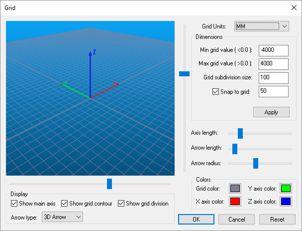
Activates the Grid dialog, which defines the boundaries and appearance of the world. The Reset button resets the grid appearance and size to reasonable values.
Grid Units can be set to any convenient value and need not match the
units used when the model was created. For optimal display and control,
the Min/
Select Grid color to set the color of the grid lines (the background
color is set in the Simulation»
The main axis (model origin), grid contour boundary and grid subdivision lines can all be toggled visible or invisible using the Display Show checkboxes.
The coordinate frame marker size, color and style can also be controlled from the Grid dialog. Three horizontal sliders control the size of the arrow. Colors for each axis of the marker can be set in the Colors area. The arrow style can be set using the Arrow type selection.