Simulation»
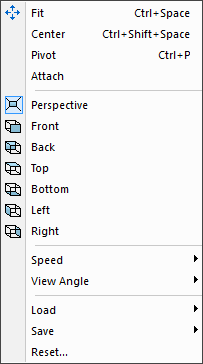
Controls various aspects of the positioning of the camera.
Simulation»
The Camera Fit function first points the camera towards the center of the currently selected object and then pans in or out so that the selected object is fully visible within the active simulation window. If no object is selected, then the camera will be adjusted to view the entire model. You can use this function to quickly reorient the camera when you are unsure of where you are pointing or if you cannot see the model. The Fit function is also available from the VM View toolbar.
When the current focus is on the Controller Time Line window, the Fit function will adjust the scale of the Time Line window so that the entire process is visible.
Simulation»
The Camera Center function points the camera towards the center of the currently selected object, or if no object is selected, then towards the origin of the Grid reference (i.e., the center of the three grids).
When the current focus is on the Controller Time Line window, the Center function will adjust the position of the Time Line scale so that the blue vertical line (marking the current time position) is visible and centered in the Time Line window.
Simulation»
The Camera Pivot function sets the center of rotation for the camera to a specific vertex of an object (Ctrl+P) or the center of the currently selected objects (Ctrl+Shift+P). The pivot center is the point in space at which the camera will aim as it is rotated. If no object is selected, then the camera will rotate about the center of the world coordinate system (i.e., the center of the three grids).
To set the camera pivot to the center of selected objects using the menu, the Shift key must be pressed while selecting the menu.
Note that setting the camera pivot this way is only available with mouse scheme that do not have another mean of setting the pivot point.
Simulation»
Attaches the camera to the currently selected object. If no object is selected, the camera is attached to the world coordinate system (this is the default). When the camera is attached to an object, the camera moves with the object. Standard viewpoints are always in relation to the attached object. The camera can also be attached to an object using the right-mouse “Attach Camera” context menu on that object. The camera can be detached by doing the same in the background. A checkmark in the menu indicates that the camera is attached to an object.
Simulation»
Switches between Perspective and Orthogonal projection in the simulation window. The Perspective projection provides a more realistic viewing of the simulation, equivalent to what you would see in the natural world. With Orthogonal projection, distance has no effect on the size of an object. Orthogonal views typically provide better control when defining part, stock and fixture objects.
Simulation»
Simulation»
Simulation»
Simulation»
Simulation»
Simulation»
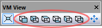
Switches the camera to one of six standard viewpoints (the VM View toolbar shown at left provides buttons for each standard viewpoint). Viewpoints are relative to the frame defined in the VM Grid toolbar (the stock axis by default).
The camera can only be panned (i.e., not rotated) when a standard viewpoint is selected. You can select and then immediately deselect a view button, to first snap to a standard view and then allow camera rotation.
Simulation»
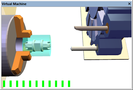
The Speed»
When adjusting the camera speed, a “volume control” type bar will appear briefly in the simulation windows to show a relative measure of the current step size.
The step size can be temporarily reduced, while panning, to 1/10th the normal amount by holding the Shift key.
Simulation»
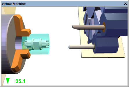
The View Angle»
When adjusting the angle, a viewing angle size indicator will appear briefly in the simulation windows.
The default viewing angle is 45 degrees. Increasing the viewing angle makes it possible to see more of the scene, at the expense of some distortion. Decreasing the viewing angle makes it possible to look at the scene in fine detail, but also makes it a little harder to navigate.
The viewing angle is used in Perspective mode only.
Simulation»
Simulation»
The Camera Save menu selection (Ctrl Alt 0 through Ctrl Alt 9) records
the current camera viewpoint, position and orientation in one of 10
standard user-defined viewpoints. The Camera Load menu selection (Ctrl 0
through Ctrl 9) resets the camera to a previously saved position. The
camera can directly switch to the new position, or it can smoothly
interpolate to the new position, if both the old and new positions share
the same underlying viewpoint (e.g., both are perspective views, or both
are front views). The Camera animation mode can be set in the
Simulation»
Simulation»
The Camera Reset menu entry resets all camera settings and moves the camera to an application default viewpoint. The reset operation also removes all saved camera viewpoints and resets the camera speed and viewing angle to the application defaults.