Adding Physical Entities to the Model
Once you have defined the kinematics framework of your machine, you are now ready to add physical entities such as tables, heads, bases, etc. These objects give substance to your model so it can be seen, but more importantly, it is the physical entities of the model on which collision testing is performed.
Entities are attached to axes or other entities in the same way that axes are attached to each other and the machine. Objects that are attached to moving axes will move when that axis moves. Sometimes, a physical entity on the machine will have some of its parts attached to one axis and the remainder attached to another axis. For example, a rotary table base would be attached to one axis (e.g., a linear axis), while the table itself would be attached to the rotary axis (so it rotates when the rotary axis moves). Another example: An X-axis table would be attached to the X-axis, but the guide-ways and base would be attached to the world.
All entities are located in terms of an XYZ offset from their parent object. An offset of zero would place the entity origin at the same position as the parent object’s origin. In the examples to this point, the axes have been defined at the machine origin. Doing so allows us to define geometry in terms of the machine coordinate frame. If machine dimensions are relative to some other position, then you should create a “Reference Axis” attached to the “Machine01” object and define the offset to the reference point used by the machine tool builder. All other objects should then be defined in the tree leading out from the reference axis.
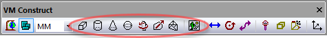
The following entity types can be created using the
Simulation»
A Cube is a box defined by its width, length and height.
A Cylinder is defined by a length and radius at each end.
A Cone is also defined by a length and radius at each end.
A Sphere is defined by a radius.
A Revolved is a 2D profile shape revolved about its local Z-axis.
An Extruded is a 2D profile shape extruded along its local Z-axis.
A Mesh is an STL object imported from the CAD/CAM system.
A Picture is a bitmap image.
All entities share some common parameters (a description of entity parameters can be found here).
Do the following to add a base, X table and C rotary table entities to the kinematics model constructed in the previous section:

Step 1: Create the base
Step 1: Create the base
Select “Machine01” in the model navigator so that the base will be defined attached to the machine.
Select Simulation»
Construct Entity» Cube. Type the following:
–1500 Enter  –500 Enter    0 Enter
 3000 Enter  1000 Enter  200 Enter
The Cube properties dialog will then appear. Type “Base” as the entity name.
Select the Material button and select or create a material color (e.g., black plastic looks nice for a base).
Press OK.
Step 2: Create the sliding table
Step 2: Create the sliding table
Select “X Axis” in the model navigator so that the sliding table will be defined attached to the X-axis of the machine. It will then move when the X-axis moves.
Select Simulation»
Construct Entity» Cube. Type the following:
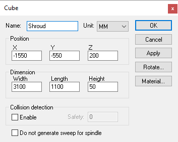
–1550 Enter  –550 Enter  200 Enter
 3100 Enter  1100 Enter   50 Enter
Type “Shroud” as the entity name.
Select the Material button and select or create a material color (e.g., silver has a nice metallic look).
Press OK.
Step 3: Create the rotary table
Step 3: Create the rotary table
Select “C Table Axis” in the model navigator so that the rotary table will be defined attached to the C-axis. It will then move when the C-axis moves (and when the X-axis moves because C is attached to X).
Select Simulation»
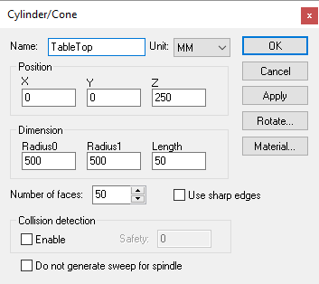
Construct Entity» Cylinder. Type the following:
  0 Enter   0 Enter  250 Enter
500 Enter  50 Enter
Type “TableTop” as the entity name.
Select the Material button and select or create a material color (e.g., pewter).
Press OK.
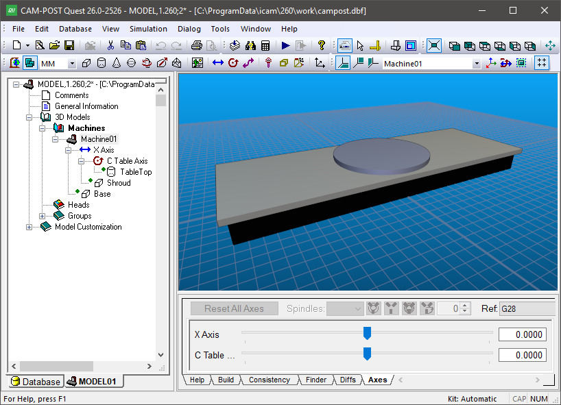
Select File»
After these steps are complete, the model and navigator should look like the image shown below.