The MODE Command [MLEPCS]
The MODE command serves many purposes. It is used to select the absolute or incremental positioning mode of the machine; to select diameter or radius X-axis output for lathes; to choose between Polar and Cartesian interpolation; to choose between RTCP or pivot point programming; to enable probe “skip” codes; to control circular arc, helical arc and spline fitting; and to control pattern fitting on a punch press machine.
The following MODE command functions are available:
Absolute vs. Incremental Positioning
The MODE command is used to change the positioning mode from absolute to incremental and vice versa. It is valid for all machine types but may not be available on specific machines.
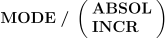
The ABSOL mode selects absolute positioning mode, if available on the machine. The INCR mode selects incremental positioning mode, again if available on the machine. While in incremental mode, axes coordinate values are defined by the difference between old and new positions.
The $PNMODE macro variable can also be used to modify the absolute vs. incremental mode.
Diameter vs. Radius Positioning
The MODE command is also used to change the X axis coordinate representation on a lathe from diameter to radius and vice versa. This command is only valid for lathes with switchable diameter/ radius control of the X axis.
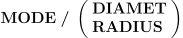
The DIAMET mode selects diameter output for the X axis, if available on the machine. The RADIUS mode selects radius output for the X axis, again provided it is supported by the machine.
The $XDIAM macro variable can also be used to modify the diameter vs. radius X axis coordinate representation mode.
Polar Interpolation
Polar interpolation (or C2P) is a feature available on most modern mill-turn lathes (i.e., lathes with a rotary C axis control). Polar interpolation allows a face milling tool-path to be output in the MCD in terms of its Cartesian XYZ coordinates on the face of the part, while the machine instead uses the linear XZ and rotary C axes to interpolate from one position to the next. Under Polar interpolation, a single block in the MCD defining a straight line motion across the face of the part will be interpolated at the machine by a complex interpolation of linear and rotary axes.
The post-processor can also emulate polar interpolation
on any machine with rotary tables, including mills, that do not have this feature, or
when machine restrictions preclude the use of built-in Polar interpolation.
Polar emulation is addressed by the MODE/
Machine Polar interpolation is controlled by the following commands:




![\icamhsp{0.707mm}\raise0.03ex\hbox{$\,\Bigl[,\textbf{TRFORM}\,\bigl[,\textbf{LAST}\,\bigr]\,\bigl[,\textbf{INVERS}\,\bigr],\mathit{x},\mathit{y}\,\Bigr]$}](../../_images/math/baf717c042d72485537fd16644fe22fc35c289ac.svg)

The AAXIS, BAXIS and CAXIS keywords are informational. If a rotary axis is specified, it must match one of the machine rotary table axes identified in the post-processor as supporting Polar interpolation.
The XAXIS, YAXIS and ZAXIS keywords are also informational. If a linear axis is specified, it must match the corresponding machine axis that will be held at its zero position during Polar interpolation.
Specify NOW to switch immediately to polar interpolation. NEXT (the default) switches to polar interpolation at the next motion that satisfies the controller requirements for polar interpolation.
By default, the origin of the Polar interpolation coordinates is at the center of the rotary axis. Use the TRFORM parameters to define a translation of the coordinate data to some other frame. The (x,y) translation amounts are applied to the Polar abscissa and ordinate axes, in that order.
The ON and OFF keywords activate and deactivate the last specified
MODE/
Polar interpolation often has special restrictions on its use. For example, some machines do not support motion along the tool axis during Polar interpolation. The post-processor will automatically switch back and forth between Polar interpolation and Polar emulation as necessary to avoid known limitations.
The LIMIT/
The MODE/
Polar Emulation
When the tool axis is parallel to one of the rotary axes, this rotary axis is called “singular”. In the case of a rotary table, it then becomes possible to use this singular rotary table axis in place of one or more linear axes when interpolating from one position to the next in the program. The use of a singular rotary table during interpolation is called “Polar” interpolation (as distinct from normal Cartesian interpolation).
Most modern mill-turn lathes provide a built-in Polar interpolation capability,
which can be addressed by the MODE/
Polar emulation is controlled by the following commands:

![\icamhsp{0.707mm}\raise0.21ex\hbox{$\begin{pmatrix}\!,\!\begin{array}{l}\begin{pmatrix}\!\begin{array}{l}\textbf{XAXIS}\\\textbf{YAXIS}\\\textbf{ZAXIS}\end{array}\!\end{pmatrix}\,\bigl[,\mathit{value}\,\bigr]\\\;\\\textbf{XYZ},\mathit{x},\mathit{y},\mathit{z},\textbf{NORMAL},\mathit{i},\mathit{j},\mathit{k}\end{array}\!\end{pmatrix}\!,$}](../../_images/math/0ba12bb6c942b699d93c2399ebecd34ed0bc43c4.svg)
![\icamhsp{0.707mm}\bigl[,\textbf{MAXDPM},\mathit{dpm}\,\bigr]](../../_images/math/d621e2ba79c588e4654fa48cd18e4c0aedf52b36.svg)
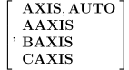
The AAXIS, BAXIS and CAXIS keywords restrict the use of polar
interpolation to the named rotary table axis only. The AXIS,
The XAXIS, YAXIS and ZAXIS
keyword and the optional value combine
to define a “constraint plane” on which the tool tip will be located
at all times. The current axis position is used if an axis value is
not specified. For example, “YAXIS,
The constraint plane can also be specified given an (x,
When a motion passes close to the rotary axis center, the rotary axis velocity will often max out at its upper limit. For polar interpolation purposes, this machine maximum rotation rate can be reduced to a more reasonable velocity by specifying the maximum degrees per minute with the MAXDPM,dpm couplet.
The ON and OFF keywords activate and deactivate the last specified
MODE/
The LIMIT/
Rotating Tool Center Point
Rotating tool center point programming (variously known as TCPM, TRAORI and RTCP) is a feature of advanced CNC controls, which compute rotary axis pivot offsets and linearization requirements in the CNC control, instead of in the post-processor. With RTCP, XYZ coordinate data and feed rate calculations are output at the tool tip and not the control point of the machine as is the traditional case. The most significant benefits of RTCP are the ability to perform tool length and diameter compensation with the head tilted at some angle to the machine XYZ axes. Other benefits include: shorter and simpler programs since they do not include linearization steps; and simpler feed rate calculations since the rotary component of the motion is not included in the feed calculation.
RTCP is controlled with the following commands:
![\icamhsp{0.707mm}\textbf{RTCP}\,\bigl[,\mathit{type}\,\bigr],\textbf{ON}](../../_images/math/8e4013ecc086f4b9ca72168b262f4465968987e5.svg)
![\icamhsp{0.707mm}\bigl[,\textbf{OPTION},\mathit{n}\,\bigr]](../../_images/math/7e78b0eebad53e1e5aa0d59bf2bdb59e24512739.svg)

ON activates RTCP programming mode; OFF deactivates RTCP mode. The optional type value specifies the type of RTCP – either 1 (the default) or 2 – when there are multiple RTCP types defined for the machine. If omitted, the last type specified will be used. The $TCPSET macro variable indicates and can change the default type.
If RTCP is not available on the controller, a diagnostic message will be output and processing will continue using normal control point output (GENER cannot emulate RTCP if it is not available on the controller). When RTCP is active, GENER will:
Output tool tip coordinates instead of control point coordinates;
Output a machine tool axis orientation using one of a number of different supported methods instead of standard rotary axes;
Inhibit linearization, while still calculating the expected control point motion for travel limitation purposes; and
Ignore the effects of RTCP enabled rotary axes on the feed rate calculations.
![\bigl[,\textbf{OPTION},\mathit{n}\,\bigr]](../../_images/math/6ffd3cd9710d1c31dc60d395c20c8eea78d4f242.svg)
Depending on controller capabilities, rotary axis positioning during RTCP mode can be controlled either by standard rotary axes values, or by special registers that define the machine tool axis
orientation. When controlling rotaries during RTCP using true rotary axes values, GENER can perform advanced linearization path planning and rotary-turn-around functions. These features are not available when controlling rotaries using other orientation methods.
The OPTION qualifier does not have to be specified since the default control method is defined in the post-processor. If a non-supported option is selected, GENER will instead use the default control method. Choices for n are:
- 0:
Do not output any rotary values.
- 1:
Output true rotary axes values.
- 2:
Output machine tool axis vector.
- 3:
Output tool-tip and tool-top points (dual curve) to define angle.
- 4:
Output RPY (roll-pitch-yaw) angles.
- 5:
Output Euler angles.
- 6:
Output custom virtual axes as defined by QUEST.
The $TCP and $TCPFMT macro variables can also be used to modify the RTCP mode.
6-Axis Post-Processing Functions
A multi-axis CL file motion contains xyz position and ijk tool
axis vector components. This provides enough information for the
post-processor to generate a 5-axis tool path consisting of up to 3
linear axes and 2 rotary axes. Additional information or constraints
are necessary to allow the post-processor to position or interpolate
6 or more machine axes. The MODE/
Cancel 6-Axis Processing

This command disables any currently active 6-axis processing.
Shared Linear Axes
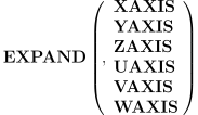
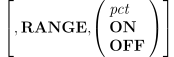
This command provides the ability to share the linear motion requirements of the program between two machine linear axes (e.g., the Z and W axes). The specified machine axis is designated as the secondary linear axis, with the primary linear axis handling all motion requirements by default. Axes are paired as follows: XAXIS with UAXIS, YAXIS with VAXIS and ZAXIS with WAXIS.
The RANGE option specifies that any motion in the selected axis is to be shared between the primary and the secondary linear axes, with the secondary linear (i.e., the named axis) being assigned the specified percentage of motion and the primary linear being assigned the remainder. OFF disables subsequent sharing of motion requirements by the secondary axis. ON enables the sharing of motion requirements at the last specified percentage (50% by default).
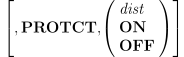
The PROTCT option specifies that when either of the primary or
secondary linear axes are within the specified distance of their
travel limitations, then the other axis is to handle the remaining
motion requirements. OFF disables the sharing of motion requirements
based on travel limitations. ON enables the sharing of motion
requirements at the last specified distance (zero by default). This
command will only have an effect if travel limits are enabled for at
least one of the shared linear axes. The LIMIT/
Tri-Rotary Interpolation
![\icamhsp{0.707mm}\raise0.31ex\hbox{$\textbf{EXPAND}\begin{pmatrix}\!,\!\begin{array}{l}\textbf{AAXIS}\\\textbf{BAXIS}\\\textbf{CAXIS}\\\textbf{AAXIS},\textbf{TABLE}\\\textbf{BAXIS},\textbf{TABLE}\\\textbf{CAXIS},\textbf{TABLE}\\\textbf{RAM}\,\bigl[,\mathit{n}\,\bigr]\end{array}\!\end{pmatrix}$}](../../_images/math/5b1425f1d7252c797a335d1e4cd1429755bbdcbf.svg)
![\icamhsp{0.707mm}\bigl[,\textbf{OPTION},\mathit{a}\,\bigr]](../../_images/math/715293303eaedf9ca55a073ecda485109c90a889.svg)
This command provides the ability to simultaneously interpolate three
rotary axes. The specified axis is designated as the third rotary
axis (see here for a table correlating axes
name keywords with machine axes). Two other machine rotary axes must
be enabled (see the CLAMP command)
for the MODE/
In general, the third rotary axis will be used for feed interpolation and the other two rotary axes will be used for positioning. For dual rotary feed interpolation, the post-processor will use the third rotary axis and whichever of the other two rotary axes whose axis of revolution is more perpendicular to the tool axis. The third rotary will not be used if doing so would cause it to overtravel.
With “OPTION,
Skip Code
The MODE/


The ON qualifier causes skip codes to be output with subsequent feed
motions until canceled by OFF; NEXT outputs a skip code with the
next motion only. The optional PART,
When GENER is running with Virtual Machine simulation, skip code processing will be simulated provided that a probe object has been defined and is active (which can be done using Virtual Machine probing functions).
Arc and Helix Fitting
The MODE/
Arc and helix fitting attempts to collect point-to-point data in the CL file and output the accumulated points as one circular or helical interpolation record on the NC machine tool. The command syntax is available on all machines that support circular or helical interpolation.

![\icamhsp{0.707mm}\raise0.03ex\hbox{$\Bigl[,\mathit{minpts}\,\bigl[,\mathit{tolerance}\,\bigr]\,\Bigr]$}](../../_images/math/ee333c0062127b294833a31077119ab5e051621b.svg)
![\icamhsp{0.707mm}\raise0.03ex\hbox{$\,\Bigl[,\textbf{DIST}\,\bigl[,\mathit{mindist}\,\bigr],\mathit{maxdist}\,\Bigr]$}](../../_images/math/d548178412ea34fbc710c23da73220c32b4e0897.svg)
![\icamhsp{0.707mm}\raise0.03ex\hbox{$\,\Bigl[,\textbf{RADIUS}\,\bigl[,\mathit{minrad}\,\bigr],\mathit{maxrad}\,\Bigr]$}](../../_images/math/fd3eaf1a2099761fdcdca766e0f406ede00bb0ff.svg)
The MODE/
![\Bigl[,\mathit{minpts}\,\bigl[,\mathit{tolerance}\,\bigr]\,\Bigr]](../../_images/math/0eaa4ab2063035cf16829a05c4cf30cba18b259f.svg)
The minpts parameter defines the minimum number of GOTO points of contiguous machining path that can be converted to an arc or helix. If not specified, a minimum of five points is required by GENER to fit a circular motion.
The tolerance parameter defines the maximum deviation of the fitted circular curve from the motions specified in CL file. If not specified, the sum of the active INTOL and OUTTOL tolerances will be used as a default.
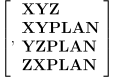
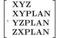
The plane selection options limit arc or helix fitting to a specified plane. By default, arc fitting is available in all planes supported by circular interpolation. The XYZ option restores fitting in all available planes.
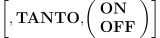
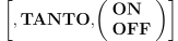
The TANTO option is used to specify continuous tangency between adjacent arcs. The default fitting mode is non-tangential (OFF), which generally results in fewer arcs having longer spans. With the tangential fitting method (ON), GENER will attempt to keep fitted arcs continuously tangent, which generally results in more arcs having shorter spans with better surface finish.
![\raise0.03ex\hbox{$\,\Bigl[,\textbf{DIST}\,\bigl[,\mathit{mindist}\,\bigr],\mathit{maxdist}\,\Bigr]$}\icamhsp{0.707mm}](../../_images/math/d6b52788e96010704dd7c6ab8f6b7ff47f4a8115.svg)
![\raise0.03ex\hbox{$\,\Bigl[,\textbf{RADIUS}\,\bigl[,\mathit{minrad}\,\bigr],\mathit{maxrad}\,\Bigr]$}](../../_images/math/7a4f85dbe8bd0bd1e1d080739327583ba5c1de78.svg)
These options are used to further limit the configuration of CL points that can be replaced by circular interpolation.
The DIST,maxdist option specifies the maximum distance between two CL points that can form an arc or helix curve. Specify a large distance value to disable this option.
The DIST,mindist,
The RADIUS,maxrad option specifies the maximum circle radius allowed. When the fitting process finds an arc or helix with radius greater than maxrad, the fitted curve is rejected and linear interpolation is used. Specify a large radius value to disable this option.
The RADIUS,minrad,
Several macro system variables also exist to control this function in finer detail.
Spline Fitting
The MODE/
Spline fitting attempts to collect point-to-point data from the CL file and output one spline interpolation curve instead. The command syntax is available on all machines that support spline interpolation.

![\icamhsp{0.707mm}\raise0.05ex\hbox{$\biggl[,\mathit{minpts}\Bigl[,\mathit{lintol}\,\bigl[,\mathit{angtol}\,\bigr]\,\Bigr]\,\biggr]$}](../../_images/math/004483d8faa3ef66aa2b8a8399fc67871623e208.svg)
![\icamhsp{0.707mm}\raise0.10ex\hbox{$\begin{bmatrix},\!\begin{pmatrix}\!\begin{array}{l}\textbf{IPM}\\\textbf{MMPM}\\\textbf{PERMIN}\end{array}\!\end{pmatrix}\,\bigl[,\mathit{fedtol}\,\bigr]\end{bmatrix}$}](../../_images/math/f134752ffb6ea68e37f359bedfe901204564dc67.svg)
![\icamhsp{0.707mm}\raise0.03ex\hbox{$\,\Bigl[,\textbf{OPTION}\,\bigl[,\mathit{minc}\,\bigr],\mathit{maxc}\,\Bigr]$}](../../_images/math/4d490d23435c4768b4418676116e16f214353531.svg)
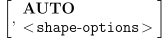

where <shape-options> are zero or more of the following:
![\bigl[,\textbf{ANGLE},\mathit{angle}\,\bigr]\icamhsp{0.707mm}](../../_images/math/869af3a898bac890e40be31f7341e01849f88ec1.svg)
![\bigl[,\textbf{TLANGL},\mathit{tlangl}\,\bigr]\icamhsp{0.707mm}](../../_images/math/13a87992f9803ffbe8d1ffa5fc7c109e645db0e0.svg)
![\bigl[,\textbf{SLOPE},\mathit{slope}\,\bigr]\icamhsp{0.707mm}](../../_images/math/2931d81e3e95df66edde83efc5aa2cc5250ad9a5.svg)
![\bigl[,\textbf{COND},\mathit{cond}\,\bigr]](../../_images/math/a1c0ce5190a599168813338686782224b492b8f2.svg)
All the SPLINE fitting parameters are optional. Coding the
MODE/
Parameter descriptions follow:
![\biggl[,\mathit{minpts}\Bigl[,\mathit{lintol}\,\bigl[,\mathit{angtol}\,\bigr]\,\Bigr]\,\biggr]](../../_images/math/133a0ebe29b5ca6a14d0b00a60cd26beb8335aad.svg)
The minpts parameter defines the minimum number of contiguous CL points that can be converted to a spline. If not specified the minimum number of points is set to 5.
The lintol parameter (linear tolerance) defines the maximum deviation of the fitted spline curve from the motions specified in the CL file. If not specified, the total sum of the active INTOL and OUTTOL tolerances will be used as a default.
The angtol parameter (angular tolerance) defines the maximum angular deviation in degrees of the fitted spline curve from the tool axis vectors specified in the CL file. This parameter is ignored for simple 3 axis spline fitting. If not specified, the angular tolerance is set to 0.01 degrees.
The XYZ option allows spline fitting for all active axes. The
XYPLAN,
![\begin{bmatrix},\!\begin{pmatrix}\!\begin{array}{l}\textbf{IPM}\\\textbf{MMPM}\\\textbf{PERMIN}\end{array}\!\end{pmatrix}\,\bigl[,\mathit{fedtol}\,\bigr]\end{bmatrix}](../../_images/math/6dc8fa68b602f397e2096b699fc1d99ea91df133.svg)
This parameter is ignored if feed rate spline interpolation is not
supported on the machine. The fedtol parameter (feed rate
tolerance) defines the maximum deviation of feed along the fitted
spline curve from the feed specified in the CL file. The feed
tolerance must be specified in one of the per/
Omitting the feed velocity tolerance removes feed rate fitting constraints from the curve calculation. Feed values will be fit on a best case basis, but will not constrain the curve fitting process. This is the default.
Note
Curve fitting only occurs for a contiguous set of motions. Post-processor commands and other CL data record types will end the curve fitting process. A change in feed rate due to a FEDRAT command cannot occur within a curve. The fedtol parameter smoothly interpolates changes of feed due to differences in travel between the machine control point and CL motion spans during 5D fitting.
![\,\Bigl[,\textbf{OPTION}\,\bigl[,\mathit{minc}\,\bigr],\mathit{maxc}\,\Bigr]](../../_images/math/33b67fb7a9cb73ed5d62725f588551129aa5e7bd.svg)
The OPTION option specifies the degree of continuity required between internal curve segments. Allowable values for minimum and maximum continuity are 0 (positional), 1 (tangential) and 2 (curvature). The curve fitter will always fit curves to the minimum continuity “minc” or better. If a curve cannot be fit to the minimum continuity, a diagnostic message will be output and the curve will be segmented. The curve fitter will attempt to fit curves to the maximum “maxc” continuity, however it is not considered an error if this is not possible.
The default maxc value is 1. The default minc value is the lesser of 1 or maxc.
Note
Curve fitting to C2 continuity takes a considerable amount of CPU. Curve fitting to C1 continuity requires moderately more CPU than curve fitting to C0 continuity. C0 curve fitting was the default for earlier releases of GENER.
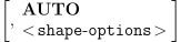
It may be desirable to limit the spline fitting and interpolation
only to some parts of the CL file. For example, when the CL file
describes machining of the mold, all motions can be divided into two
groups: surface machining and other motions. We may want to apply
spline interpolation for surface machining and leave other motions as
they are. In the case where a CAD system does not output
any information allowing to recognize whether a tool motion
represents a surface cut, the “shape-options” of the MODE/
Usually, the cut across the surface will be represented by a series of short linear cuts. They will be stored in the CL files in a multi-point GOTO records (record class 5000, subclass 5 and 6).
The AUTO option specifies that only tool positions that are defined
by multi-point GOTO CL records are subject to spline fitting. This
option is mutually exclusive with all point selection options that
are based on the geometrical properties (distance, slope,
Within a series of short linear motions representing a surface cut, the distance between consecutive points tends to be of the same magnitude. The same can be said about the changes of the motion direction and the changes in the direction of the tool axis. Having said that, the behavior “tends” to be like that, it does not mean that it always will. Therefore some process of trail and error may be required before finding the combination of control parameters that allows correctly recognize the motions for which spline interpolation needs to be applied.
When more than one optional condition is specified, all of them must be satisfied before a point is accepted for spline fitting.
![\,\Bigl[,\textbf{DIST}\,\bigl[,\mathit{mindist}\,\bigr],\mathit{maxdist}\,\Bigr]](../../_images/math/75f7284a83fbaf4789fcfcb4df34f707c9e63a43.svg)
The DIST,maxdist option specifies the maximum distance between two CL points that can form a spline curve. In order to turn the option off specify a large distance value (equal to or greater than machine limits).
The DIST,mindist,
![\bigl[,\textbf{ANGLE},\mathit{angle}\,\bigr]](../../_images/math/2168510024e48ae578c604623b9f47ab2ba1c9e5.svg)
The ANGLE,angle option specifies the maximum angle between two consecutive motions. If the angle between two motions exceeds this maximum, spline fitting ends at the last accepted position. In order to turn the option off specify an “angle” value equal to or greater than 180 degrees.
![\bigl[,\textbf{TLANGL},\mathit{tlangl}\,\bigr]](../../_images/math/5669502b09ed5528c2466cb4f0879fff174ec5bc.svg)
The TLANGL,tlangl option specifies the maximum angular distance between tool axis vectors at two consecutive CL points. If the angle between two tool axis vectors exceeds this maximum, the spline fitting ends at the last accepted position. In order to turn the option off specify a “tlangl” value equal to or greater than 180 degrees.
![\bigl[,\textbf{SLOPE},\mathit{slope}\,\bigr]](../../_images/math/7374cb0744170b0f92862854a288b270fa6b32aa.svg)
The SLOPE,slope option is used to control the rate of the direction change between two consecutive motions. If the angle between two motions is A and the length of the current and next motion is LMC and LMN then the value of “slope” is expressed as:
slope = A / (LMC + LMN)
The SLOPE,slope parameter specifies the maximum allowed rate at which motion direction can change when moving along cutter path. If the maximum is exceeded, the spline fitting ends at the last accepted position. In order to turn the option off specify a “slope” value equal to or greater than (90 degrees / one machine linear pulse).
The COND,cond option is used to measure homogeneity of the motion direction changes within two consecutive tool motions. If the angle between two motions is A and the length of the current and next motion is LMC and LMN then the value of “cond” is expressed as:
cond = A * max(LMC,
LMN) / min(LMC, LMN)
This measure tells that the change in motion direction is more significant if one of motions is much shorter than the other. This is because the change happens “more locally”, over a shorter distance. If motion homogeneity condition exceeds the specified maximum, the spline fitting ends at the last accepted position. In order to turn the option off specify a “cond” value equal to or greater than (180 degrees * max motion length / one machine pulse).
Several macro system variables also exist to control this function in finer detail.
Linearization is automatically activated during 5D spline fitting.
This ensures that the tool tip is well behaved while the machine
rotary axis are moving. By default, linearization attempts to keep
the tool tip moving along a straight line from one CL file point to
the next. A new spline interpolation option changes this behavior,
linearizing instead to a locally interpolated curve passing through
the CL file points (in Icam parlance, this is called a throwaway
curve). This feature is controlled by the following MODE/

The resulting LINTOL generated intermediate points tend to match the
results that would be obtained by tightening the tolerance in the CAM
system. These intermediate points are then used by the spline fitting
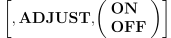
algorithms when construction the final curve. We recommend that
ADJUST,
When the goal is to maximize the use of spline interpolation, spline
fitting can count the total number of output data points (including
those generated by LINTOL) instead of input CL file points. This
feature is controlled by the following MODE/

MODE/
Turning Curve Fitting Off
Arc and spline fitting is turned off by the command:

If arc and spline fitting are active at the same time, the first fit is attempted with the entity type that has the higher minimum number of points requirement.
CIRCUL and SPLINE parameters can be coded on the same MODE command.
Pattern Fitting

The pattern recognition mode is activated when the pattern fitting
section is answered in QUEST, This MODE/
The minpts specifies the minimum number of points that are needed to define the pattern. The tolerance option specifies the deviation that can be allowed for the points forming the pattern.