Simulation»
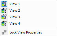
Provides access to up to four individual Virtual Machine simulation windows — View 1 through View 4 — each of which can be shown or hidden by toggling its corresponding menu item. Selecting a View item displays the window if it is hidden or minimized, or hides it if already visible. The Lock View Properties option determines whether view-related settings (such as projection mode or camera orientation) are shared across all visible windows. When locked, changes to one window are applied to all; when unlocked, each window can be configured independently.
The visibility of the “View 1” simulation window can also be toggled from the View toolbar.
It is important to note that collision/
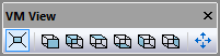
Simulation windows supports both Perspective and
Orthogonal projection, selectable by the leftmost button in the VM
View toolbar. The middle six buttons of the VM View toolbar orient
the camera to face the Front, Back, Top, Bottom, Left and Right views
of the machine. The camera can only be panned but not rotated while
one of these standard views is selected. At the start of processing,
standard views are with respect to the stock mount point, but this
can be changed by selecting a different component (e.g., the machine
origin) in the VM Grid toolbar or by attaching the camera to an
object in the scene (more on grids and attaching the camera to
components later). The rightmost button in the VM View toolbar
adjusts the camera aim and zoom (in that order) to fit the currently
selected object so that it is fully visible in the simulation window
(if no object is selected, then the camera is adjusted so all objects
can be seen). All of these toolbar functions are also available from
the Simulation»
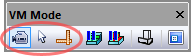
The three buttons on the left side of the VM Mode toolbar
select the primary function of the left-mouse button (this can also
be set from the Simulation»
When in Camera mode, press and hold the Ctrl key to temporarily switch to Selection mode. This can be used to quickly select objects to rotate about or to attach the camera to. When in Selection or Measurement mode, press and hold the Ctrl key to temporarily switch to Camera mode. This can be used to get a better view of the object you are trying to select or measure.
It is important to remember that with VM, you are moving (or flying) a camera through a three dimensional scene. Changing your viewpoint typically involves some combination of panning, rotation and roll.
Panning moves the camera up, down, left, right, as well as in and out of the scene. When in perspective mode, you can pan the camera through an object to see beyond it. When in orthogonal mode, panning in and out instead acts like a typical zoom lens.
Rotation changes where the camera is pointing, by angling it to the left, right, up or down (i.e., pitch and yaw). Camera rotation is similar to the actions of turning your head to the left or right and up or down. Camera rotation is only possible when a standard view (e.g., front, back) is not selected, since views lock out camera rotation.
Roll tilts the camera so that objects can be viewed from a different angle. Camera roll is similar to the action of tilting your head to the left or right.
The Simulation»
Camera panning
The following is a list of panning navigation functions. Hold the
Shift key while panning to reduce the distance the camera moves to
1/10th the normal amount. You can adjust the overall panning
sensitivity by holding the Ctrl key and repeatedly pressing the +
(plus) and – (minus) keys (also available from the
Simulation»
Pan
Key
Mouse
Up
Page Up
Middle-mouse, move forward
Down
Page Down
Middle-mouse, move backward
Left
Left arrow
Middle-mouse, move left
Right
Right arrow
Middle-mouse, move right
In
Up arrow
Mouse wheel forward
Out
Down arrow
Mouse wheel backward
Camera rotation
Move the mouse while holding down the left-mouse button to change the viewing direction of the camera. There are two types of camera rotation.
The default rotation is to keep the camera position fixed but to change where the camera is aimed. This is similar to how we rotate our head to look around a scene.
You can hold the Shift key to change how the camera rotates. When Shift is pressed, the camera rotates around a point in space. This rotation point is by default the center of the world or the selected VM Grid object, but can be changed by selecting any object and choosing Simulation»
Camera» Pivot (Ctrl P). As a quick shortcut, double-clicking an object in a simulation window will set that object as the Pivot center and fit the object in the window.
If you prefer the second form of camera rotation by default, clear
the “Default to Look-Around camera” checkbox in the
Simulation»
You can quickly orient the camera to point at the center of the
currently selected object using the Simulation»
The following is a list of camera rotation functions available when in Camera mode. Note that camera rotation is not available when a VM View filter is enabled (e.g., Front, Side…).
Rotate
Mouse
Up
Left-mouse, move forward
Down
Left-mouse, move backward
Left
Left-mouse, move left
Right
Left-mouse, move right
Camera roll
The camera is oriented so that “up” is along the positive Z direction (of the selected VM Grid object) in all views except Top and Bottom, where “up” is instead along the positive Y direction. The following keys can be used to roll (i.e., tilt) the camera clockwise or counterclockwise.
Roll
Key
90° cclw
Ctrl Left arrow
1° cclw
Ctrl Shift Left arrow
90° clw
Ctrl Right arrow
1° clw
Ctrl Shift Right arrow
Camera origin and attachment
You can attach the camera to an object in the scene. If the object moves, so will the camera. This can be done using the right-mouse “Attach Camera” context menu selection, which will show a check mark to indicate that the camera is attached to an object. To detach the camera, right-mouse in the background and again select Attach Camera to reset the camera back to the world origin.
The Simulation»
Camera viewpoint
The creator of the machine model can (and should) define a series of predefined views (not to be confused with the standard perspective, front, rear, etc. views described earlier) to simplify viewing the model during simulation. These might show a full view of the machine, a detailed view of the table, perhaps a view from the tool’s perspective and so on. In the absence of any view information, VM will show the machine with the camera placed well back in the negative machine Y-axis direction.
To switch between predefined views, press one of the keyboard number
keys 0 through 9 while holding down the Ctrl key. If the display does
not change, then that view number is undefined. You can define your
own viewpoints by holding down the Ctrl and Alt keys before pressing
a number key. Default views are stored with the model; personal
viewpoints are stored in the vsw file where they override those of
the model. Predefined views can also be activated and set using the
Simulation»
The transition between views can be abrupt or smooth, depending on
the camera animation setting in the Simulation»
To summarize
The Simulation»
Left-mouse controls camera rotation.
Middle-mouse and mouse wheel control panning.
Right-mouse brings up a context sensitive menu.
Left / Right / Up / Down arrows and Page Up / Down also control panning.
Ctrl Left / Right arrows roll the camera cclw and clw.
Shift modifies all of above functions.
Left-mouse double-click does a Fit (Ctrl Space) and Pivot (Ctrl P) on the selected object.
Ctrl P sets the camera pivot origin to the selected object.
Ctrl Space (or Ctrl .) reorients and zooms the camera to “fit” the object in the window.
Ctrl Shift Space reorients the camera to point at the selected object.
Ctrl 0 through Ctrl 9 selects one of 10 prerecorded camera positions.
Ctrl Alt 0 through Ctrl Alt 9 saves prerecorded camera positions.
Simulation»
Options (Ctrl Alt O) sets camera animation and look-around properties.