The HEAD Command [LEC]
The HEAD command is used to control selection and synchronization of heads on a 4-axis merging lathe, synchronize motions between the lower and upper wire guides of a 4-axis wire EDM and to control the contouring head on a contouring machine or hybrid punch press.
Merging Lathes
On a 4-axis lathe, one head may be moving while the other is idle, or both heads may be moving together. The first mode of operation is called the “non merge mode” and the latter is called the “merge mode”. The user can control the mode of operation of a 4-axis lathe using the HEAD command.
The Non-Merge Mode
In the non-merge mode, one head (the main or the side head) is moving, while the other remains idle.

HEAD/
Consider the following example:
ISN
…
0012 HEAD/MAIN
0013 TURRET/1,1
0014 GOTO/1,1
…
0029 COOLNT/OFF
0030 HEAD/SIDE
0031 TURRET/1,2
0032 GOTO/2,2
…
0043 AIR/OFF
0044 HEAD/MAIN
0045 GOHOME
0046 FINI
In the above example of the non merge mode of operation, commands
from ISN 13 up to 29 are performed by the main head because of the
HEAD/
The last GOHOME command is performed by the main head, again because
of the HEAD/
The Merge Mode
In the merge mode, the two heads of a 4-axis lathe move together (i.e., are synchronized).
![\textbf{HEAD}\;\textbf{/}\;\bigl[\,\textbf{MANUAL},\bigr]\begin{pmatrix}\!\begin{array}{l}\textbf{BOTH}\\\textbf{OFF}\end{array}\!\end{pmatrix}](../../_images/math/e279d233fd9c490d22738ff73c1fa867aa9a022e.svg)

![\icamhsp{0.707mm}\raise0.05ex\hbox{$\bigl[\,\textbf{MANUAL},\bigr]\begin{pmatrix}\!\begin{array}{l}\textbf{MAIN}\\\textbf{SIDE}\end{array}\!\end{pmatrix}$}](../../_images/math/53de4d40a35900927abb8aea5120454ad291be0b.svg)
![\icamhsp{0.707mm}\bigl[,\textbf{SPINDL},\mathit{n}\,\bigr]](../../_images/math/4612cc9b99d0e9eeb9d875a8fe09d81112bd9891.svg)
HEAD/
Specifying the optional keyword MANUAL will inhibit the output of synchronization codes to the MCD, however GENER will continue processing as though the synchronization codes were output.
When MAIN and SIDE heads are operating on the same turning spindle with constant surface speed spindle mode in effect, the controlling spindle can be specified using the optional SPINDL,n couplet, where n defines the controlling spindle. A value of 1 indicates that the MAIN head X axis controls the spindle RPM and a value of 2 indicates that the SIDE head X axis controls the spindle RPM. If the controlling spindle is not specified, or is specified as zero (0), then GENER will internally assign the controlling spindle to whichever head first processes a SPINDL command.
The following is a valid sequence of commands used in the merge mode:
ISN
…
0012 HEAD/BOTH
0013 HEAD/MAIN,SPINDL,1
0014 TURRET/1,1
0015 FEDRAT/50,IPM
0016 GOTO/…
…
0020 GOTO/HOM1
0021 HEAD/SIDE,SPINDL,1
0022 COOLNT/ON
0023 TURRET/2,2
0024 FEDRAT/80,IPM
0025 GOTO/…
…
0029 COOLNT/OFF
0030 HEAD/OFF
In the above example of merged mode of operation, commands from ISN
14 up to 20 are performed by the main head because of the HEAD/
![\icamhsp{0.707mm}\bigl[\,\textbf{MANUAL},\bigr]](../../_images/math/45619dab506a06f77adaee259fe7ab2a7468046e.svg)
![\icamhsp{0.707mm}\textbf{NEXT}\,\bigl[,\mathit{value}\,\bigr]](../../_images/math/2c27b8164d496ca323195152a4b91a46bb45d011.svg)
Synchronization between a merge pair occurs at the start of each
pair. Synchronization can also be achieved within a merge pair using
the HEAD/
Specifying the optional keyword MANUAL will inhibit the output of
synchronization codes to the MCD, however GENER will continue
processing as though the synchronization codes were output. The head
controlling the spindle constant surface speed can also be specified
using the optional SPINDL,n couplet, as described above for the
HEAD/
There are several ways to achieve the same result using different
HEAD syntax. The example below illustrates this. The three columns
describe different methods to achieve the same tape output. The first
column has two HEAD/
HEAD/BOTH
HEAD/MAIN               HEAD/BOTH                   HEAD/BOTH
goto/m1                 HEAD/MAIN                   HEAD/MAIN
HEAD/SIDE               goto/m1                     goto/m1
goto/s1                 HEAD/SIDE                   HEAD/NEXT
HEAD/OFF                goto/s1                     goto/m2
HEAD/BOTH               HEAD/SIDE                   HEAD/SIDE
HEAD/SIDE               goto/s2                     goto/s1
goto/s2                 goto/s3                     HEAD/NEXT
goto/s3                 HEAD/MAIN                   goto/s2
HEAD/MAIN               goto/m2                     goto/s3
goto/m2                 HEAD/OFF                    HEAD/OFF
HEAD/OFF
GENER uses a switching method, based on the predicted processing time of the buffered commands for each head. The first head section of the pair will always be started first. In merge mode, GENER will output tape until the accumulated time for the current head is greater than the accumulated time for the other head. When the time for the other head is less, GENER switches to the other head. This minimizes the amount of time that either head remains idle.
To allow for maximum head synchronization, the END, OPSTOP, REWIND and STOP commands should not be coded while in the merge mode, although they are allowed in non-merge mode.
4-Axis Wire EDM Machines
On a 4-axis wire EDM, complex 5-axis shapes can be programmed using MULTAX to include the wire orientation information for each end point (swarf cut). GENER can also merge two independent 2-axis contours for the lower and upper wire guides to produce complex 5-axis shapes. The first mode of operation is called the “non merge mode” and the latter is called the “merge mode”. The user controls the mode of operation in merge mode using the HEAD command.
The syntax of the HEAD command for 4-axis EDMs is as follows:
![\textbf{HEAD}\;\textbf{/}\;\textbf{BOTH}\,\bigl[,\textbf{STEP}\,\bigr]](../../_images/math/fd2e0f6395b231db9921aa60784d90307f4db50a.svg)

![\textbf{HEAD}\;\textbf{/}\;\textbf{NEXT}\,\bigl[,\mathit{value}\,\bigr]](../../_images/math/6379c2931ba3d234226e2cb685d1a38ded07ed9c.svg)
The Non-Merge Mode
In the non-merge mode, all motions refer either to the lower wire guide, the upper guide, or to a logical program position in line with both guides. The actual position used is controlled using the PIVOTZ command. Both guides are controlled by individual motion points, with or without associated tool axis vectors. No HEAD commands are necessary.
The Merge Mode
In the merge mode, the two guides of a 4-axis EDM move together.
HEAD/
The following is a valid sequence of commands used in the merge mode:
ISN
…
0012 HEAD/BOTH
0013 HEAD/LOW
0014 GOTO/…
…
0020 GOTO/…
0021 HEAD/HIGH
0022 GOTO/…
…
0029 GOTO/…
0030 HEAD/OFF
In the above example of merged mode of operation, commands from ISN
14 up to 20 are performed by the lower guide because of the HEAD/
Synchronization between a merge pair occurs at the end of each pair.
Synchronization can also be achieved within a merge pair using the
HEAD/
There are several ways to achieve the same result using different
HEAD syntax. The example below illustrates this. The three columns
describe different methods to achieve the same tape output. The first
column has two HEAD/
HEAD/BOTH
HEAD/LOW                HEAD/BOTH                   HEAD/BOTH
goto/m1                 HEAD/LOW                    HEAD/LOW
HEAD/HIGH               goto/m1                     goto/m1
goto/s1                 HEAD/HIGH                   HEAD/NEXT
HEAD/OFF                goto/s1                     goto/m2
HEAD/BOTH               HEAD/HIGH                   HEAD/HIGH
HEAD/HIGH               goto/s2                     goto/s1
goto/s2                 goto/s3                     HEAD/NEXT
goto/s3                 HEAD/LOW                    goto/s2
HEAD/LOW                goto/m2                     goto/s3
goto/m2                 HEAD/OFF                    HEAD/OFF
HEAD/OFF
If the STEP keyword is specified on the HEAD/
If the STEP keyword is omitted, GENER merges lower and upper wire guide motions based on the distance traveled between synchronization points. Additional interpolated motions may be inserted as necessary into the upper or lower guide paths to maintain a proper final wire path.
To allow for proper guide synchronization, the END and REWIND commands cannot be coded while in the merge mode.
Contouring Heads
Contouring heads are supported on contouring machines and hybrid punch press machines with contouring attachments.
The syntax of the command is as follows:
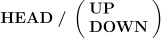
The first command causes the contouring head to move up and away from the workpiece. The second command causes the contouring head to move into the workpiece.