The LIMIT Command [MLEPC]
The LIMIT command is used: to activate and deactivate travel limit checking; to shift or transform the coordinate data for travel limit purposes; to define a preferred rotary alignment of the machine where feasible; to avoid linear overtravel conditions through the application of polar interpolation; and to automatically orient singular rotary axes to position the workpiece so as to avoid linear overtravel conditions. This command is available for all machine types.
Travel Limit Checking
The following command is used to define, activate and deactivate up to 10 different travel limit checking zones:


![\icamhsp{0.707mm}\bigl[,\mathit{zone}\,\bigr]](../../_images/math/5e9fecd06e097cdb183fc4da29271d637d1454eb.svg)
![\icamhsp{0.707mm}\raise0.68ex\hbox{$\icamrange{13.1}{1}\!\begin{pmatrix}\!,\!\begin{pmatrix}\!\begin{array}{l}\textbf{XAXIS}\\\textbf{YAXIS}\\\textbf{ZAXIS}\\\textbf{UAXIS}\\\textbf{VAXIS}\\\textbf{WAXIS}\\\textbf{QUILL}\\\textbf{AAXIS}\\\textbf{BAXIS}\\\textbf{CAXIS}\\\textbf{AAXIS},\textbf{TABLE}\\\textbf{BAXIS},\textbf{TABLE}\\\textbf{CAXIS},\textbf{TABLE}\\\textbf{RAM}\,\bigl[,\mathit{n}\,\bigr]\end{array}\!\end{pmatrix}\!,\!\begin{pmatrix}\!\begin{array}{l}\bigl[\,\textbf{ON},\bigr]\begin{pmatrix}\!\begin{array}{l}\mathit{low},\mathit{high}\\\mathit{total}\end{array}\!\end{pmatrix}\\\;\\\textbf{OFF}\end{array}\!\end{pmatrix}\end{pmatrix}$}](../../_images/math/86de6599fe5db50fdf8bd164724f50e826ca0ce8.svg)
The initial ON or OFF indicates whether the travel limit checking should be enabled or disabled respectively for a zone. If omitted, ON is assumed (i.e., travel limit checking is enabled).
IN and OUT describe two types of range checking zones. IN zones define a specific area where the axes are permitted to travel. The axes must remain inside of the limits specified. OUT zones define a specific area where the tool axes are not permitted to travel. The axes must remain outside of the limits specified. If this parameter is omitted, IN is assumed.
If only one value is given for a particular axis, limit checking for that axis will be based on total travel rather than on a travel range. Total travel limit checking is only valid for IN zones.
The zone parameter is a scalar value identifying the travel limit zone. There are 10 zones available: zone one (1) represents the travel limits predefined by the post-processor creator; zones 2 through 10 can be defined by the NC programmer. If the zone number is not specified, one (1) is assumed (in other words, predefined limits).
See here for a table correlating axes name keywords with machine axes.
The low and high parameters specify the minimum and maximum limits in machine coordinates for the named axis. The total parameter specifies a total travel limit in machine coordinates for the named axis. In either case the ON keyword is optional. The OFF keyword can be specified to turn off travel limit checking for the named axis. For example, the following program segment turns off any travel limit checking predefined by the post-processor creator, moves the machine and then turns the predefined travel limit checking back on.
LIMIT/OFF
GOTO/0,0,0
GOTO/0,0,4
LIMIT/ON
This next example defines two new travel zones that are used depending on the circumstances. Initially zone 1 is enabled and zone 2 is disabled.
LIMIT/ON,IN,1,XAXIS,-10,40,ZAXIS,5,15
LIMIT/OFF,IN,2,XAXIS,-3,47,ZAXIS,2,13
The following commands are needed to turn zone 1 checking off and turn zone 2 checking on:
LIMIT/OFF,1
LIMIT/ON,2
Any or all of the ten available zones may be active at one time. The machine axes will be permitted to travel in the intersection of the active zones.
For total travel limits, axis travel is accumulated starting from the time that the limit is activated. If a total travel limit is turned off and then turned on again later, GENER will stop keeping track of total travel while the limit is inactive and will then resume when the limit is re-activated.
Travel Limit Tool Compensation
The following command offsets the linear axes, for travel limit calculation purposes only, in order to account for controller tool compensation using expected gauge lengths or offsets.
![\textbf{LIMIT}\;\textbf{/}\;\textbf{LENGTH},\bigl[\,\mathit{x},\mathit{y},\bigr]\,\mathit{z}](../../_images/math/734a66530a6a9b34d7cd0437639be68aa55e1af7.svg)
The LIMIT/
In the following example, the LIMIT/
LIMIT/ON,2,IN,ZAXIS,0,10
LIMIT/LENGTH,4
GOTO/0,0,6    $$ ok
GOTO/0,0,-4   $$ ok
GOTO/0,0,-5   $$ exceeds minimum
GOTO/0,0,7    $$ exceeds maximum

Likewise, the LIMIT/
In the following example, a LIMIT/
LIMIT/ON,2,IN,ZAXIS,0,10
LIMIT/SETOOL,0,0,-4
GOTO/0,0,6    $$ ok
GOTO/0,0,-4   $$ ok
GOTO/0,0,-5   $$ exceeds minimum
GOTO/0,0,7    $$ exceeds maximum
Travel Limit Fixture Compensation
The following command offsets the linear axes, for travel limit calculation purposes only, in order to account for controller fixture (i.e. workpiece) compensation amounts.

The LIMIT/
The LIMIT/
Travel Limit Frame Transformation
The LIMIT/
Note
The LIMIT/
The syntax is:
![\textbf{LIMIT}\;\textbf{/}\;\textbf{TRFORM}\,\bigl[,\textbf{LAST}\,\bigr]\begin{pmatrix}\!,\!\begin{array}{l}\mathtt{<\!matrix\!>}\\\textbf{ON}\\\textbf{OFF}\end{array}\!\end{pmatrix}](../../_images/math/f423b9dfdc37bada4a49c4d44485c82e3cecef99.svg)
Two separate transformations can be applied and removed individually.
LIMIT/
The <matrix> defines the location and orientation of the resultant after-transformation coordinates on the machine, with respect to the normal coordinates. The matrix can be specified using the standard post-processor transformation syntax (see “The ORIGIN Command [MLEPC]”).
When LIMIT transformation is active, the linear axes column displays and travel summaries show coordinate data in the “as transformed” state.
The ON and OFF keywords enable or disable travel limit transformations. OFF ignores the effect of the matrix. ON re-establishes the previously specified matrix.
Preferred Rotary Solution – Modulo-360 Range
The following command is used to define, for a specific rotary axis, a preferred modulo-360 range of rotary travel (typically within 180 degrees) to be used on 5-axis positioning motions, so as to influence the choice of rotary solution (or pose) from the two possible solutions normally available for any given tool axis vector.

![\icamhsp{0.707mm}\raise0.31ex\hbox{$\begin{pmatrix}\!,\!\begin{array}{l}\textbf{AAXIS}\\\textbf{BAXIS}\\\textbf{CAXIS}\\\textbf{AAXIS},\textbf{TABLE}\\\textbf{BAXIS},\textbf{TABLE}\\\textbf{CAXIS},\textbf{TABLE}\\\textbf{RAM}\,\bigl[,\mathit{n}\,\bigr]\end{array}\!\end{pmatrix}$}](../../_images/math/27d5beb81fb7247326f1cd32fb7d31f673cccfff.svg)
![\icamhsp{0.707mm},\mathit{low}\,\bigl[,\mathit{high}\,\bigr]](../../_images/math/4392c3f8c5112a748640cde9a77b830860233a18.svg)

Rotary solution choices are only available on non-linearized (i.e.,
LINTOL/
The low and high parameters define the lower and upper machine coordinate limits of the preferred positioning range for the named axis. The high parameter defaults to low+180 if omitted. All angles are treated as modulo-360. (Use the physical range command described below to instead define an absolute range of preferred travel.)
GENER will choose the solution that respects the following condition for the named axis, where all angles are modulo-360:
low ≤ angle < high
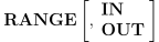
IN and OUT can be used to define an inclusive or exclusive preferred positioning range. IN is the default and defines an inclusive range as shown above. OUT can be used to define an exclusive range, where the preferred solution avoids the defined range.
Once a preferred rotary solution has been specified, ON and OFF can be coded without an axis value to enable or disable preferred rotary solution positioning.
Preferred Rotary Solution – Physical Range
The following command is used to define, for one or more rotary axis, a preferred physical range of rotary travel to be used on 5-axis positioning motions, so as to influence the positioning of the rotary axes, especially in cases where the rotary range is finite but exceeds 360 degrees.
![\icamhsp{0.707mm}\raise0.10ex\hbox{$\begin{pmatrix}\!,\!\begin{array}{l}\mathit{low}\,\bigl[,\mathit{high}\,\bigr]\\\noalign{\vskip 0.5ex}\textbf{ON}\\\textbf{OFF}\end{array}\!\end{pmatrix}$}](../../_images/math/cd0d07b63d6781421c2f94a95a9369a4fed235c3.svg)

Rotary range choices are only available on non-linearized (i.e.,
LINTOL/
The low and high parameters define the lower and upper machine coordinate limits of the preferred positioning range for the named axis. All angles are treated as absolute angles. (Use the modulo-360 range command described above to instead define a modulo-360 based preferred solution.)
GENER will choose the solution that respects the following condition for the named axis, where all angles are absolute:
low ≤ angle < high
IN and OUT can be used to define an inclusive or exclusive preferred positioning range. IN is the default and defines an inclusive range as shown above. OUT can be used to define an exclusive range, where the preferred solution avoids the defined range.
Preferred positioning ranges can be specified for each rotary axis. Once a preferred range specification has been given for a rotary axis, preferred range selection for that specific axis can subsequently be enabled or disabled by coding ON or OFF in place of the range specification.
Once a preferred range has been specified for any rotary axis, ON and OFF can be coded without an axis name to enable or disable preferred range positioning for all axes.
Limit Based Cartesian-Polar Switching
When the tool axis is parallel to
one of the rotary axes, this rotary axis is called “singular”.
In the case of a rotary table, it
then becomes possible to use this singular rotary axis in place of one or
more linear axes when positioning or interpolating from one position
to the next in the program. The use of a singular rotary axis in
place of a linear axis is called “Polar” interpolation (as distinct
from normal Cartesian interpolation), which can be controlled using
the MODE/
The basic syntax is:

The LIMIT/
Polar Interpolation Switching

The CNC keyword specifies that machine polar interpolation should be used if necessary to avoid overtravel conditions. This requires GENER to perform a path-planning look-ahead each time it encounters a RAPID or high feed positioning motion. This look-ahead will analyze all of the cutting motions that immediately follow, to determine if polar interpolation is necessary so as to avoid an overtravel condition.
At the completion of the look-ahead, GENER will do one of the following:
Activate machine polar interpolation for the positioning motion(s) and all of the following cutting motions.
Deactivate polar interpolation if active and optionally pre-position the singular axis if necessary to avoid overtravel for the positioning motion(s) and all of the following cutting motions.
Polar Emulation Switching
![\icamhsp{0.707mm}\raise0.21ex\hbox{$\icamrange{4.66}{1}\!\begin{pmatrix}\!,\!\begin{array}{l}\begin{pmatrix}\!\begin{array}{l}\textbf{XAXIS}\\\textbf{YAXIS}\\\textbf{ZAXIS}\end{array}\!\end{pmatrix}\,\bigl[,\mathit{value}\,\bigr]\begin{bmatrix},\!\begin{array}{l}\textbf{LARGE}\\\textbf{SMALL}\end{array}\!\end{bmatrix}\\\;\\\textbf{XYZ},\mathit{x},\mathit{y},\mathit{z},\textbf{NORMAL},\mathit{i},\mathit{j},\mathit{k}\end{array}\!\end{pmatrix}$}](../../_images/math/29e1f5414cb457f1fb41eb5bc215f9b4ca463a4e.svg)
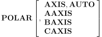
The AAXIS, BAXIS and CAXIS keywords restrict the automatic use of
polar interpolation to the named rotary table axis only. The
AXIS,
The XAXIS, YAXIS and ZAXIS
keyword, the optional value and the
LARGE-SMALL couplet, all combine to define a “guard plane” and zone
of travel where Cartesian positioning is valid. The post-processor
will use polar emulation (i.e., rotate the singular axis) to avoid
moving the named axis to the opposite side of the guard plane. The
current axis position is used if an axis value is not specified.
LARGE is assumed if neither LARGE or SMALL is specified. For example,
“XAXIS, –0.5,
The guard plane and zone of travel can also be specified given an
(x,
A maximum of four guard planes can be defined. These planes do not have to be orthogonal (i.e., are not required to be parallel or perpendicular to each other).
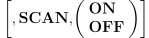
The SCAN,
When entire path cannot be optimized in one step, having defined RTA sequence allows the motion to be broken just before the overtravel and to apply additional rotation at the safe RTA sequence. The process will be then automatically repeated as many times as needed.
Starting from V25, the Cartesian-Polar travel optimization can
be also applied to the sequence of CYCLE points. Set $PLR230=
Polar Switching Activation

OFF disables limit based Cartesian-Polar switching. ON re-enables the last specified Cartesian-Polar switching selection (i.e., interpolation or emulation).
The LIMIT/
Limit Based Singular Positioning
When the tool axis is parallel to one of the rotary axes, this rotary axis is called “singular”. In the case of a rotary table, it then becomes possible to use this singular rotary axis in place of one or more linear axes when positioning from one location to the next in the program. The use of a singular rotary axis to position the workpiece is called “Polar” positioning (as distinct from normal Cartesian positioning).
The LIMIT/
The syntax is as follows:

![\icamhsp{0.707mm}\raise0.10ex\hbox{$\begin{bmatrix},\!\begin{array}{l}\textbf{INCR},\mathit{delta_{1}}\Bigl[,\mathit{delta_{2}}\bigl[,\ldots\,\bigr]\,\Bigr]\\\noalign{\vskip 1.0ex}\textbf{ABSOL},\mathit{value_{1}}\Bigl[,\mathit{value_{2}}\bigl[,\ldots\,\bigr]\,\Bigr]\end{array}\!\end{bmatrix}$}](../../_images/math/8cce308f4b9d5782805e6b548aff68badd454297.svg)

The “INCR,delta1,delta2,
The “ABSOL,value1,value2,
The SCAN,