MCD Based Simulation with CATIA V5
This section describes the processing flow to prepare, post-process and MCD simulate a manufacturing process using CATIA V5. In order to perform MCD based simulation you must have both a Control Emulator run-time license (cer270) from Icam and a CATIA V5 Machine Tool Simulation license (MPS) from Dassault Systèmes.
Machining and Simulation Setup
CATIA must be first setup to use Icam software products before you can post-process a generated aptsource file with Icam Post GENER, or MCD simulate a generated NC program using CERUN and DELMIA
To perform the setup, start CATIA and then select Tools»
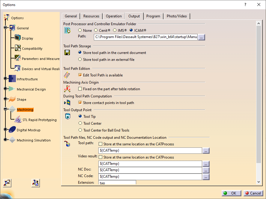
Select Machining in the navigator on the left side of the dialog, and then choose the Output tab along the top. The default settings are normally appropriate, with the following exceptions:
Select Icam for the Post Processor and Control Emulator Folder.
Edit the NC code output Extension and change it from CATNCCode to “tap” (or whatever default extension you are using with Icam Post GENER).
Next, choose Machining Simulation»
Select the “Display Tool Path during Simulation” checkbox if you would like to see a trace of the tool tip motions during machine simulation.
Select the “Enable material removal computation” checkbox to have DELMIA perform in-process stock material removal calculations during machine simulation.
Your preferences will be remembered from one CATIA session to the next.
Part Operation Settings
CATIA has the concept of a “Part Operation” node in the PPR tree, which contains general information about the manufacturing process. The following Part Operation dialog settings are of interest when post-processing or when simulating the MCD.
Part Operation»
The stock accuracy setting defines the level of detail of in-process stock calculations. There is a trade-off between increased accuracy and CPU/RAM requirements. The finer (i.e., smaller) the accuracy, the longer it will take to compute in-process stock and the greater the memory requirements will be.
Part Operation»
These settings define the default collision checking behavior during tool path simulation; not the behavior when using CERUN to perform MCD based machine simulation with a DELMIA model.
The Part Operation must be setup to run with a DELMIA machine model in order to perform MCD based simulation. This is done by selecting the button with the image of an NC machine at the upper left of the Part Operation dialog. The field to the right of the machine button lists the current machine selection. Select the button to view or change the machine settings.
Machine Editor»
This field identifies the selected machine model. To choose a DELMIA machine model, select one of the “Assign” buttons at the upper right and browse for and open a CATProduct containing the DELMIA machine model. This will update the Name and Comment fields to those defined in the model.
Depending on the creator of the model, some or all of the Machine Editor fields discussed below may be set read-only to inhibit changes to a production model.
Machine Editor»
Select the control emulator to use in the “Control Emulator” drop-down field. The available choices are limited to those control emulators that are defined in the Icam database that was associated to CATIA by the CAM Integration setup utility (see “Setup CERUN”). Control emulators are created using QUEST, as described in “QUEST”.
The remaining Machine Editor settings primarily affect post-processing.
Select the post-processor to use in the “Post Processor” drop-down field. The available choices are limited to those post-processors that are defined in the Icam database that was associated to CATIA by the CAM Integration setup utility.
Select an appropriate Icam pptable in the “Post Processor words table” drop-down field. A pptable is a text file that defines the syntax of aptsource that is generated by CATIA. Each post-processor vendor has its own unique vocabulary that it expects to find in the aptsource file. The pptable naming convention is hopefully descriptive enough to guide your choice.
Select ISO as the NC data type, to tell CATIA to run the post-processor when generating NC code. If APT is chosen instead, then CATIA will generate an aptsource file but will not call up post-processing nor will it be possible to automatically associate the MCD file of the manufacturing program for machine simulation.
Select Axis (X,Y,Z,I,J,K) when simulating a 4 or 5-axis mill or a 4 or 5-axis mill/
turn center. Select Point (X,Y,Z) when simulating 2 or 3-axis mills or 2-axis lathes. For best results, select all of the 3D linear, 2D circular, 3D circular and Helical interpolation checkboxes. Only select the 3D Nurbs interpolation checkbox if the manufacturing program will be run on a machine that has an Icam supported spline interpolation format. Note that Icam Post GENER V27 does support spline interpolation, but Control Emulator CERUN V27 does not yet support this form of interpolation.
The remaining settings also affect how the aptsource is generated and therefore how the program will be post-processed and later simulated. Use the F1 key to obtain detailed information on the effect of each of these settings.
Machine Editor»
Select the “Radius compensation” checkbox to have the ability to define tool length and tool radius compensation offsets. If this checkbox is not selected, each tool can only have a single tool compensation offset associated with it. When selected, it will be possible to associate multiple corrector numbers to a tool using the Tool Definition dialog box (first select More and then select the Compensation tab).
Machine Editor»
This panel defines the home point of the machine at the start of processing. This information is normally not editable.
Machine Editor»
This panel defines the rotary axes available on the machine, their centers of rotation and their travel limits. This information is normally not editable.
Machine Editor»
This panel defines how 3D contact cutter compensation information is output to the aptsource file. Note that Icam Post GENER and Control Emulator CERUN do not yet support this form of compensation.
Machine Editor»
This panel defines additional formatting details of the aptsource file.
Press OK to save the Machine Editor settings, then OK again to save the Part Operation settings. These settings will be remembered for the current manufacturing process only.
Post-Processing with GENER
The Part Operation settings should be used to select the post-processor, PPTable and other aptsource generation options (as described in the preceding section) before attempting to generate or simulate MCD code.
MCD can be generated from CATIA in either interactive mode or batch mode. With batch mode, the post-processor is run from a separate process of CATIA, so that the current session is not held up during post-processing. Unless post-processing routinely takes a long time to complete, the interactive mode of MCD generation should be used. The CATIA interface is nearly identical.
To create the MCD file for the current manufacturing process, right click on the manufacturing program and navigate the pop-up menu to the “Generate NC Code Interactively” selection. You can also use the NC Output Management toolbar to choose between the “Generate NC Code Interactively” and “Generate NC Code in Batch Mode” selections. A “Generate NC Output…” dialog will appear, with the following settings that may be of interest when post-processing.
Generate NC Code»
The Input CATProcess can only be modified when batch processing, otherwise the current process is listed. The top-most selection window allows you to restrict or enlarge the choice of manufacturing programs to post-process simultaneously.
The NC data type input field must be set to “NC Code”. The “One file for all selected programs” radio button must be selected since Icam Post GENER only accepts a single aptsource file as input.
The Output File is the name of the MCD file that will be generated by post-processing. The file extension of the output MCD file is defined in the CATIA Tools»
Options» Machining» Output settings (see “Machining and Simulation Setup”). If the post-processor has been setup to output a different file extension (i.e., QUEST “General Description/ Output Format” question #110), then CATIA will be unable to automatically associate the generated MCD file with the manufacturing program. In this case, the MCD file can be manually selected when simulating (see “MCD File Selection Override”).
Generate NC Code»
The settings on the tool motions tab have an effect on the aptsource generated just prior to post-processing. The DELMIA model builder can “lock” these settings to ensure consistency in how the aptsource is generated. Tool motion settings control: the presence or absence of GOTO motion commands under various conditions; the use of RAPID in the program or following a tool change; and the use and limitations of circular interpolation.
Generate NC Code»
The settings on the formatting tab have also have an effect on the generated aptsource and as above, the DELMIA model builder can “lock” these settings to ensure consistency in how the aptsource is generated. Formatting settings control: the precision of linear and angular motions; and control the level of detail and type of program commentary.
Generate NC Code»
Use this panel to override the post-processor originally selected in the “Part Operations»
Machine Editor» Numerical Control” settings. The [?] button will display information about the selected post-processor. Select the More Options checkbox to activate the GENER launch panel before post-processing begins. The launch panel can be used to set the program ID, define user parameters that perhaps are required by the post-processor and to adjust any of the other various settings that control post-processing. The GENER launch panel is fully described in the Icam Post V27 User Guide.
Press Execute to begin post-processing. The post-processor has a number of different interface styles that it can use when running, as set by the CAM Integration setup utility (see “GENER UI”).
CATIA will signal the end of interactive post-processing by popping up a message box indicating successful completion, or listing the number of errors and warning diagnosed in both the aptsource and MCD generation phases of processing.
CATIA will not signal the end of batch post-processing.
MCD File Selection Override
CATIA will try to automatically associate the post-processed MCD file
to the manufacturing program. This automatic association will only
work if the post-processor does not override the MCD file name from
the suggested default (see “Generate NC Code»
To override the MCD file associated to the current manufacturing program, right click on the manufacturing program and select “Definition” from the pop-up menu (or double-click on the program name in the PPR list). A dialog will appear as shown below:
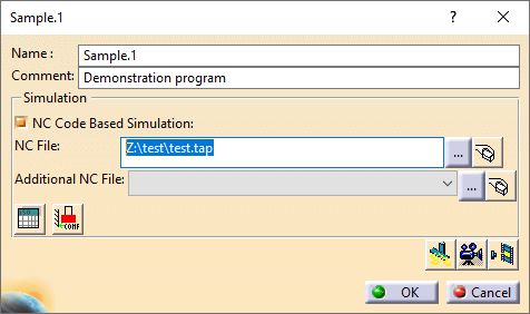
Select the “NC Code Based Simulation” checkbox, if it is not already selected, to enable MCD based simulation. The “NC File” selection will list the default associated MCD file. Use the […] button to browse for a different MCD file to use.
The “Additional NC File” selection is currently not used by Control Emulator. If simulating a program that includes one or more user subprograms, these subprograms must be attached to the end of the main program MCD file. Controller resident subprograms are normally included in the Control Emulator itself and therefore need not be specified with the CATProcess.
Tool and Workpiece Compensation Settings
To define tool and workpiece compensation settings for the current manufacturing process, right click on the manufacturing program and navigate the pop-up menu to the “Definition” selection. The “MCD File Selection Override” dialog will appear (as shown with two buttons in the lower left corner that control tool and workpiece compensation settings.
Cutter Compensation Panel
The “Cutter compensation management for simulation” panel is used to define the tool compensation amounts that will be used during control emulation. These settings are saved with the CATProcess. A sample panel is shown below:
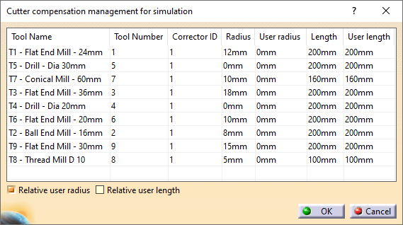
The Tool Name column lists all tools defined in the program, along with a Tool Number and a Corrector ID. The same tool number may have multiple entries, one for each different corrector ID used in the program, but the combination of tool number and corrector ID should be unique.
The Radius and Length columns list the nominal tool radius
and tool length as defined in the tool resource. The User radius
and User length columns list the values that will be used for
diameter and length compensation for the tool/
Select the “Relative user radius” checkbox if diameter compensation on the machine is set to the difference between the nominal and actual tool diameter. When this box is checked, the default User radius is zero for all tools and CATIA should be offsetting the tool path from the surface by the nominal tool radius amount. Clear the checkbox if diameter compensation on the machine is set to the measured tool diameter. When this box is cleared, the default User radius is the nominal radius and CATIA should be outputting the tool path at the surface of the material. To change a radius for testing purposes, first select the tool compensation row by clicking anywhere in the row with the left-mouse button. Click a second time on the User radius column. Type the new radius offset amount and then press Tab or select elsewhere on the dialog to set the offset amount.
Similarly, select the “Relative user length” checkbox if tool length compensation on the machine is set to the difference between the nominal and actual tool diameter. When this box is checked, the default User length is zero for all tools and the post-processor should be offsetting the tool path along the tool axis by the nominal tool length amount. Clear the checkbox if length compensation on the machine is set to the measured tool length. When this box is cleared, the default User length is the nominal length. The tool length compensation can be changed for testing purposes in the same way as described above for tool diameter compensation.
At the start of control emulation, CERUN reads the cutter compensation table and stores the offset amounts, which it applies when the appropriate tool length and/or tool diameter offsets are selected. The offset amounts are applied in the DELMIA model; they do not appear in the CERUN output trace window.
Origin Compensation Panel
The “Workpiece origin management panel” is used to define the workpiece compensation offsets that will be used during control emulation. These settings are saved with the CATProcess. A sample panel is shown below:
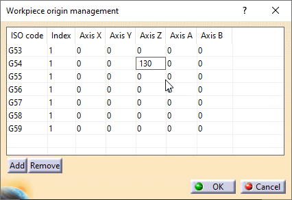
The ISO code column lists a series of workpiece compensation
codes, one per row, suitable for machines using G53-G59 series
workpiece compensation. If the CNC machine uses some other code
(e.g., G505-G599) or code/
To modify a listed Axis offset value, first select the offset row by clicking anywhere in the row with the left-mouse button. Click a second time on the axis column to be changed. Type the offset amount and then press Tab or select elsewhere on the dialog to set the axis offset amount.
The Index column is not used by Control Emulator.
At the start of control emulation, CERUN reads the ISO code values as listed in this table and loads the axes offset values for each workpiece compensation code that it recognizes. The offset amounts are applied in the DELMIA model; they do not appear in the CERUN output trace window.
Using CERUN with CATIA
Two forms of MCD based simulation are available. To select the type of simulation, right click on the manufacturing program and navigate the pop-up menu to one of the following selections:
Video Simulation using NC Code simulates the motions of the tool with respect to the part, showing the material removal process as it is expected to occur at the machine. The machine is not visible or checked for collisions and over-travel during a video simulation. Unlike a tool path simulation that is based on the aptsource file, NC code video simulation is based on the MCD file and takes into account the machine Kinematics.
Machine Simulation using NC Code simulates the motions of the machine and tool, showing the material removal process as it is expected to occur at the machine. As with the video NC code simulation, machine simulation is based on the MCD file and takes into account the machine Kinematics.
If the CATProcess has been updated more recently than the MCD file, you will be prompted to regenerate the aptsource file before continuing on to simulation. Answer Yes to regenerate, in which case both the post-processor and control emulator will be run. Answer No to use the MCD file as defined, in which case the control emulator will only be run if it has not yet processed the MCD file.
See “Using CERUN with Virtual Machine” for a description of the CERUN interface and how to use it. Note that when running with DELMIA, CERUN does not use the Virtual Machine simulation windows, because the simulation will be shown later inside CATIA after CERUN has completed.