CAM Integration Setup
Icam Post integrates to a variety of CAM systems through the use of the CAM Integration setup utility, which provides the means to associate V27 and other versions of Icam Post with CAM systems for which integration is available. Once this association is made, Icam post-processors can then be selected from within the CAM system when post-processing. Also, Icam manufacturing “extractors” can be run from within the CAM system to obtain manufacturing data (such as tools, holders, parts and fixtures) to be used with Virtual Machine simulation.
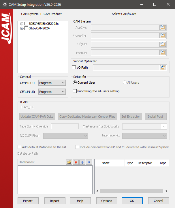
To start the CAM Integration setup utility from the Start menu, first locate the “Icam V27 x64” Start menu, then select “CAM Integration”. To start the utility from the portal, select the Tools pane and click on the “CAM System Integration Utility” tile or icon. The utility will appear as shown below (depending on what CAM systems are installed on your computer):
CAM Selection
The setup utility will search for and list in the Main tab all of the supported CAM systems installed on the computer, including their build numbers and the directories where they are installed. First select the checkbox beside a CAM system interface name, and then select the 270 checkbox to associate the current V27 release with that CAM system. The setup utility will then show the integration settings required for the selected CAM system.
The following CAM interfaces were available at the time of publication:
3DEXPERIENCE 2015x–2025x
CATIA V5R21, V5-6R2012–2025
Cimatron 2025
Creo 7-11
FeatureCAM 2017–2025
Fusion 360 2021-2025
GibbsCAM 2024–2026
Mastercam 2019–2025
NX12, 1847, 1872, 1899, 1926, 1953, 1980, 2007, 2206-2412
PowerMill 2021–2025
If a supported CAM system is known to be installed on the computer but does not appear in the list, then select the OPTIONS button, clear the “Show only Installed CAD/CAM systems” checkbox, and press OK to see a list of all supported CAM systems. Select the checkbox beside the desired CAM interface as above, however in this case the “AppExe” entry (identifying the CAM system executable file installed on the computer) will have to be manually updated.
Clear the checkbox beside a CAM system name to remove the association between it and Icam products. Information previously entered will be remembered and reapplied should the checkbox be re-enabled at some later time. Similarly you can clear the checkbox beside an Icam product version to remove the association between that Icam version and the CAM system.
The OPTIONS dialog “Show only integrated Icam and CAM products” checkbox can be selected to list only those CAM systems that currently have an association with an Icam product.
The OK button exits the setup utility, saving all changes. The Cancel button exits the setup utility, ignoring any changes done to checkboxes on the Main tab (however, all other changes done to individual CAM system tabs will not be reverted).
CAM integration settings are stored in the HKEY_LOCAL_MACHINE registry. Select the EXPORT button to save these settings to a ZIP file. The IMPORT button can be used to restore previously saved CAM integration settings, or to copy them to another computer. CAM and Icam software installation file paths must be the same when exporting and importing saved settings between computers.
CAM Integration
Each CAM system associated with Icam products will have its own unique tab containing integration settings required for that CAM system. An example is shown below.
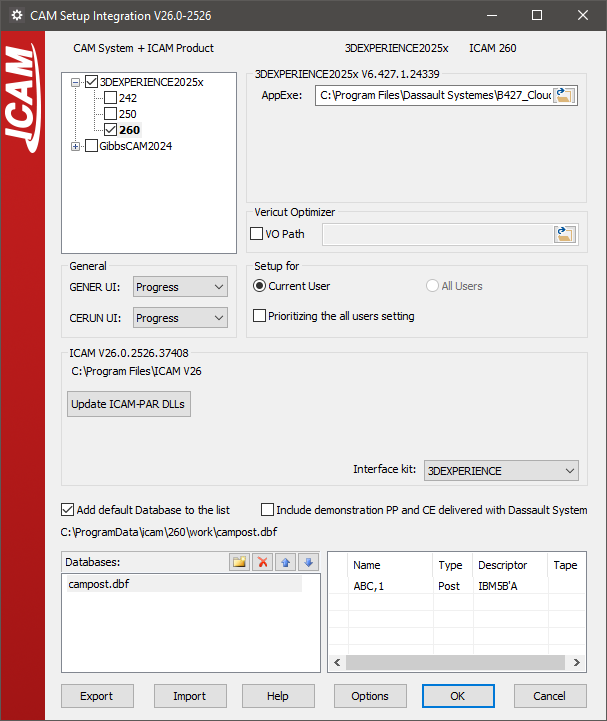
Below the CAM system name there will be one or more checkboxes, one for each version of an Icam product that can be associated with selected CAM system. For example, select the 270 checkbox to integrate V27 with the CAM system. Clear the checkbox to remove the association of V27 with the CAM system.
The following settings are common to all CAM system setup tabs:
GENER UI and CERUN UI: These select the default interface to use when running the post-processor or control emulator started from within the CAM system. The choices are the same as those available on the launch panel.
Setup for Current user vs. All users: These control where setup information will be stored in the Windows Registry. Individual user setup takes precedence over all-user setup.
AppExe or AppDll: This selects the main executable file or library for the CAM system. The setup utility uses this information to determine the build release number and installation directory of the CAM system. Additional directory path information is required for some CAM systems. This field will have already been set if the CAM system was automatically detected.
Interface kit: This setting selects the interface kit to use during post-processing.
Add default database to the list: Select this checkbox to include the default Icam database for the current Icam version in the list of databases below it. Multiple databases can be integrated, by browsing for each database and adding them to the list. The Delete, Up and Down buttons can be used to manage the list of databases and the order in which the CAM system will list the available post-processors. Select a database to see a list of objects it contains.
Depending on the CAM system, varying degrees of integration are available to allow selection of an Icam post-processor or activation of an Icam Manufacturing Extractor from within the CAM system.
CATIA and 3DEXPERIENCE: The post-processors and control emulators in the database will be available for selection in the Part Operation / Machine Editor / Numerical Control settings. If the “Include demonstration…” checkbox is enabled, then demonstration post-processors and control emulators will also be available for selection. If the post-processors are not listed in the CAM system as expected, then a possible solution is to update the DLLs that manage the interface by selecting the “Update Icam-PAR DLLs” button. Icam provides up-to-date copies of these DLL’s in the Icam installation directory, which can be used if the currently installed DLL’s are out of date. This button will be disabled if the DLLs are already up-to-date.
To post-process, right-mouse on a manufacturing process and select “Generate NC Output Interactively”. The Execute button will run Icam Post GENER using the post-processor name as selected above. The “NC Code” tab provides a drop-down where a different post-processor can be selected if necessary. The “More Options” checkbox will run the launch panel instead of the “GENER UI” interface type selected in the setup utility.
To simulate NC code, right-mouse on a manufacturing process and select “Simulate Machine using NC Code”. This will run Control Emulator using the “CERUN UI” interface type selected in the setup utility. Once completed, a “Process Simulation” dialog will appear in CATIA and 3DEXPERIENCE providing control over the simulation.
Creo: First, select the Icam Productivity Tools database file using the browser button in the “Databases” area. The post-processors contained in the selected database will appear in the adjacent area. Select the post-processors required to be made available in Creo and click the “Install Post” button.
The “Set Extractor” button must be used if Icam Virtual Machine needs to also be integrated.
Both buttons update the Creo “protk.def” file, which must be registered using the Creo Auxiliary Applications function. New toolbar options labeled “Icam Post” and “Icam Extractor” will then become available when editing Creo NC manufacturing assemblies.
FeatureCAM: Currently, you cannot directly control the post-processor and control emulator from within FeatureCAM. Instead, you can use the Icam manufacturing extractor to post-process or control emulate the manufacturing process currently opened in FeatureCAM.
To do so, first run CAM integration for the appropriate version of FeatureCAM, which sets the Icam Productivity Tools database that you can use with the Icam Extractor. Next, open FeatureCAM, and in the Add-Ins tab &Add-Ins section, select the “Manage…” button. Browse to select “integration\
FeatureCAM\ Win64\ CPlugin.dll” from the Icam product installation directory. Re-open FeatureCAM and you can now access the “IcamMfgExtractor” Add-In on the Macros section of the Add-Ins tab. Select this button to run the Icam manufacturing extractor, which you can use to extract data out of FeatureCAM for post-processing and simulation. Mastercam: First select the post-processors to be available from Mastercam and then press the “Install Post” button, which creates PST entries for the selected posts. For an Icam post-processor to be usable from within Mastercam, it is recommended that you first create the Machine Definition and then create the Control Definition that will identify the PST file. This Machine and Control combination can then be used to identify the post-processor to use for an NC program. Use the G1 button to start post-processing.
The “Copy Dedicated Mastercam Control files” button copies the contents of a selected directory to the Mastercam Shared directory. Use this to install in Mastercam the custom dedicated post-processor Machine and Control definitions supplied by Icam Technical Support.
The “Set Extractor” button creates an “IcamExtractor.FT” file in the Mastercam Chook directory, which can then be used to create an “IcamExtractor” toolbar button in the Mastercam standard toolbar (this is done automatically in Mastercam for SolidWorks). Select the IcamExtractor button to run the Icam manufacturing extractor.
NX: First, select the CLSF template that you would like to use from the “NX CLSF Files:” drop down list. In addition to the standard NX CLSF templates, Icam provides a custom CLSF template, ICAMCLSF, which creates APT-like cls files.
Next, select the post-processors that should be available for selection in NX, and press the “Install Post” button. This will first make the CLSF template available in the NX “CLSF Output” dialog and then make the selected post-processors available for selection in the NX “Postprocess” dialog.
PowerMill: Currently, you cannot directly control the post-processor and control emulator from within PowerMill. Instead, you can use the Icam manufacturing extractor to post-process or control emulate the manufacturing process currently opened in PowerMill.
To do so, first run CAM integration for the appropriate version of PowerMill, which makes the Icam Plugin available in PowerMill. Next, open PowerMill and you can access the Icam Plugin in the Vertical Plugin Window. Select the “Start Extractor” button to run the Icam manufacturing extractor, which you can use to extract data out of PowerMill for post-processing and simulation.