
Integration Utility Kit Return to previous
 ICAM MFGExtractor for PowerMill

- CAM System: PowerMill 2015/2016/2017
- Company: Autodesk, Inc
- Website:www.autodesk.com
- Release: 22.0-1712
ICAM MFGExtractor for PowerMill
Overview
Thanks for choosing Icam Post, the NC post-processing product from Icam Technologies Corporation.
ICAM unified manufacture extractor, automatically retrieves all necessary information (include tool path, process, machine setup, tools, product geometries etc.) from PowerMill to run the Adaptive Post-Processing, Simulation and Optimization sequence.
Start Extractor
To start Mfg-Extractor correctly, PowerMill must be installed and loaded correctly.
-
Start Extractor by choosing the correct version of Extractor
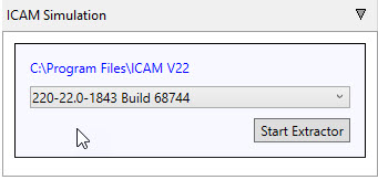
-
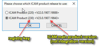
Select product release to use if there's more than one ICAM product were set for this CAM.
If there's more than one ICAM product release were set for this PowerMill version, user can choose which release to use.
ICAM Manufacture Extractor
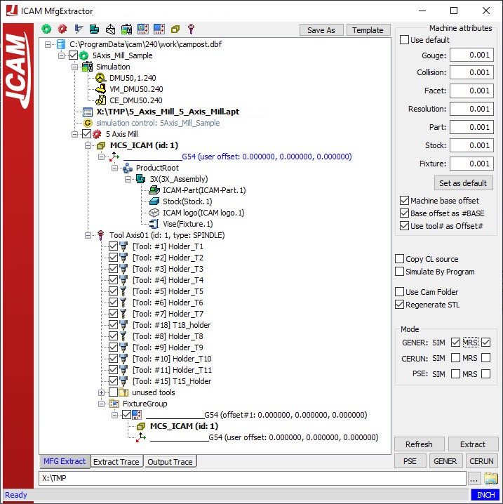
Manufacturing Settings
This section is the main section of the Extractor. It allows you to control some of the manufacturing settings for the simulation.
At the top, you have the ICAM specific settings used to define your post processor, control emulator, and virtual machine. If there are multiple products, you can right-click
the category and select one from the list.
You can also change the CL file or the NC file.
The following section contains all the extracted information from your CAM system such as your part, stock, fixture, and tools.
Each manufacturing process is considered one program, each with their associated elements.
The coordinate system axis is used to position your stock, part and fixture inside ICAM's virtal machine. It is known as the stock axis. If you require an additional offset,
you can edit the values between the parenthesis.
Product Root
Below the stock axis, you can find the product root consisting of all extracted geometry. The exactror organizes them between 3 groups: part, stock, and fixture.You can right-click on each node to assign them to the different types. Note that the extractor can automatically recognize preset geometry.
A special None type can be used to ignore certain geometries when extracting the information to Virtual Machine.
Below the product root, you can find all the tools extracted from your ICAM system. Only the used tools will show a checkmark. The unused tools can be found hidden under an expandable
button.
Finally, there's information about all the work offset available. The values shown in the bracket are relative to the stock axis value, any additional offset, and the settings from the
machine attributes.
Machine Attributes
This section is used to set the tolerances. The tolerance settings are an important part for proper simulation. The tolerance settings can be separated into 2 distinct categories: VM tolerances and STL tolerances. The values are based off the unit system shown at the bottom right corner of the extractor.
- The gouge tolerance represents the amount of collision authorized between the tools and finished part.
- The collision tolerance is related to the collisions with the environment elements such as your fixtures. By default, this value can be relatively large, understanding that the machine elements usually have safety zones defined.
- The facet tolerance defines the tessallation used in revolution solids calculation such as a rotating spindle. It is also used for the tool shape tolerance relative to the analytical definition.
- The resolution tolerance controls the tool path resolution.
- The part, stock, and fixture tolerance defines the tessallation for each of the different geometries.
Finally, you can use the button to set as default values if you have made changes.
The Machine base offset and Base offset as #Base are used by the software to calculate the work offset value when importing the CAM elements inside virtual machine.
- Case 1: If none of the boxes are checked, then the value of the virtual machine work offset will not take account the diffence between the tool axis and stock axis.
This will not affect the intertal work offset value.
Fixture compensation = CAM fixture compensation - Case 2: If Machine base offset is checked alone, then the value of the virtual machine work offset will take account the difference between the tool and stock axis.
This will affect the internal work offset value.
Fixture compensation = CAM fixture compensation + base offset - Case 3: If Machine base offset and Base offset as #Base is checked , then the value of the virtual machine work offset will take account the difference between the tool and stock axis.
This will not affect the internal work offset value. It will add the difference to a #Base offset instead.
Fixture compensation = CAM fixture compensation
Simulation fixture compensation #BASE = base offset
Working Folder
At the bottom, you can choose a folder to save all the extracted elements and information.
Output Settings
Under the machine attributes, there are more settings that controls the output settings.
- Copy CL source will set the extractor to copy over the CL or NC source file to your working folder.
- Simulat by Program is used when multiple manufacturing operations exists within the same process. You can split them into their own simulation to simulate them individually or simulate them sequentially.
- Use CAM Folder forces the working folder to be the same as the CL File location.
- Regenerate STL is used to regenerate the STL files of the generated geometries.
Mode
Under the Mode tab, you have the option to run the different ICAM products with or without simulation. Similarly, you can choose to enable material removal (MRS) or not.
- GENER is for post processing.
- CERUN is for G-code processing.
- PSE is for both post and G-code processing.
Preference options
More options are available under the preference options window. To access this window, you must right-click the extractor top bar, using the selection window, go to preference options.
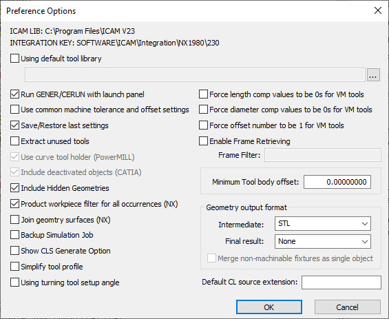
This window provide additional options which are either generic or specific to a CAM system, shown in bracket.
General Settings
- Using default tool library is used when an external tool library use is preferred. This library have tools that differ from the exported tools from the CAM system.
- Run GENER/CERUN with launch panel is used when you want to have the ICAM launch UI appear. This will allow you to make some final changes to post processing or G-code emulation.
- Save/Restore last settings is used to save all your Extractor setting for the current job. Such that, if you close the Extractor, you will be able to reopen it with all the same changes you have made.
- Extract unused tools is used to extract any tools that are not used, but were created in the CAM system.
- Include hidden geometries is used to extract any geometries that are hidden in the CAM.
- Backup simulation job is used to create an additional job file as backup.
- Simplify tool profile is used to recalculate the tool profile to keep the minimum number of line segments based on the current facet tolerance.
- Using turning tool setup angle is used to set the default turning tool angle based on the tooling information.
- Force length comp values to be 0s for VM tools is used to force a value of 0 for any length compensation value inside Virtual Machine.
- Force diameter com values to be 0s for VM tools is used to force a value of 0 for any diameter compensation value inside Virtual Machine.
- Force offset number to be 1 for VM tools is used when you need to have your length and diameter offset numbers to be 1.
- Enable frame retrieving is used to retrieve the coordinate system embeded in the product, and to set it as a FRAME (coordinate system) in Virtual Machine. It's name must containt the Frame filter string.
- Minimum tool body offset: is used to offset the body of a parametric tool. A positive offset reduces the diameter of the tool body.
- Geometry output format is used to change the file format of the extracted geometry. An additional option allows you to merge non-machinable fixtures to be a single object.
- Default CL source extension: is used to tell the extractor what is the default CL or NC source extension.
PowerMill Specific Settings
- Use curve tool holder is used to