Integration Utility Kit Return to previous
 ICAM MFGExtractor for Creo
- CAM System: PTC Creo 1,2,3,4,5,6,7
- Company: PTC, Inc.
- Website: www.ptc.com
- Release: 22.0-1702
ICAM Unified Manufacture Extractor for Creo Documentation
Overview
Thanks for choosing Icam Post, the NC post-processing product from Icam Technologies Corporation.
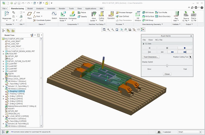
ICAM unified manufacture extractor, automatically retrieves all necessary information (include tool path, process, machine setup, tools, product geometries etc.) from Creo to run the Adaptive Post-Processing, Simulation and Optimization sequence.
Prequisite
- Creo must already be installed on the computer before running the Extractor
- Creo integration must have already been set
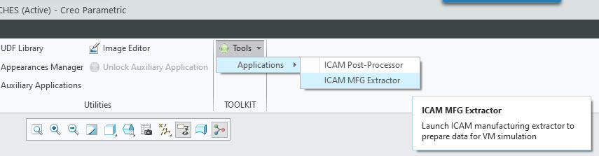
Start ICAM MFG-Extractor
In a manufacturing session, the ICAM MFG-Extractor is available under the Tools -> TOOLKIT.
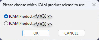
Select product release to use
If more than one ICAM product release were set for this Creo version, a window will appear with radio buttons. Select the ICAM version to launch, then press OK.
ICAM Manufacture Extractor
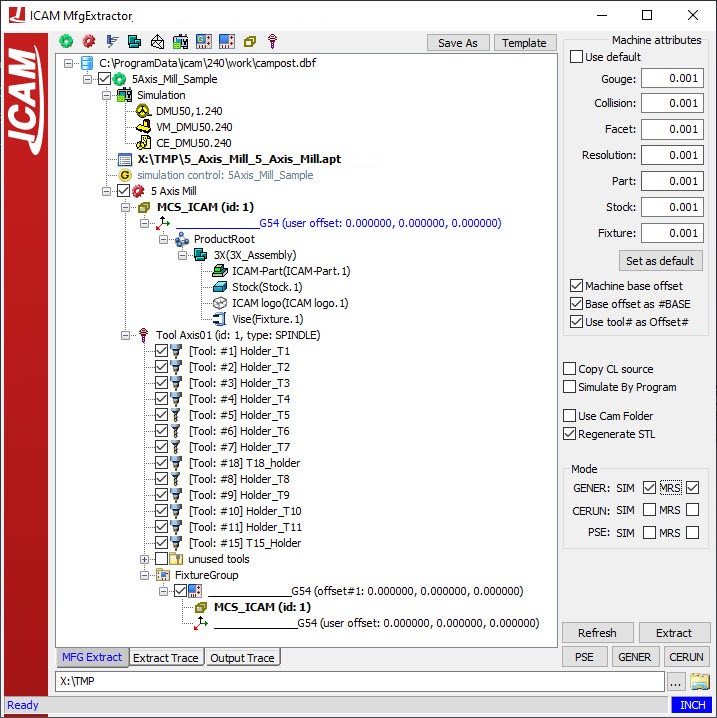
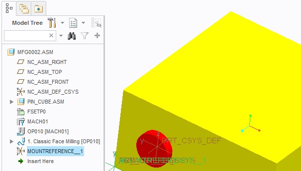
Extractor Tree Nodes
- Simulation Setup Root: Shows the full path and filename of the ICAM database selected during the extractor setup.
- Machine Setup Group: Same as the program tree node in NX which is the parent to all subsequent manufacturing data (e.g., NC_PROGRAM or name of the program).
- ICAM Resources Group:
- Post-processor
- Virtual Machine Model
- Control Emulator
- Cutter Location Source File: The default path and filename used by NX when generating CL data.
- Simulation Job: The name of the simulation job to be launched.
- Program Group: A repository for parts, stocks, fixtures, tool paths, and tools.
- VM Stock Axis: The name of the Stock Axis defined in the VM model.
- Mounting Reference: The coordinate system associated with the Machine Setup Group (right-click to select an alternate system).
- Product Root:
- Part: The name of the reference design model.
- Stock: The name of the stock model or assembly.
- Fixture Assembly: The name the fixture used in the setup group.
- Unassigned Objects: Undesignated components.
- Toolpath Group: Lists the operations from the program.
- Operation 1
- Operation 2
- VM Tool Axis: The name of the Tool Axis defined in the VM model. Lists the tools used
in the program.
- Tool 1
- Tool 2
- FixtureGroup: Lists the fixture offset, VM stock axis, and mounting reference as children.
- Fixture Offset
- Stock Axis
- Mounting Reference
- Fixture Offset
- VM Stock Axis: The name of the Stock Axis defined in the VM model.
Using the Extractor
Typical interaction with the ICAM Extractor UI window includes:
- Verifying the simulation resource tree components. If any changes are required, right-click to reassign:
- Simulation Setup: Select another CAM-POST database.
- ICAM Resources: Select another PP, VM or CE contained in the same database.
- Cutter Location Source File: Select another CL file or NC program.
- Mounting Reference: Select a different coordinate system defined in NX.
- Product Geometry Group components: Reassign elements as Part, Stock, Fixture or None.
- The VM Tool Axis: Select a different axis if multiple tool axes are defined in VM.
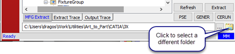
- Verifying the Working Directory at the bottom of the UI (select a different folder if required)
- Verifying the Tolerance settings in the upper-right area of the UI:
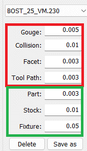
- VM tolerances (Gouge, Collision, Facet, Tool path).
- STL tolerances (Part, Stock, Fixture)
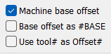
- Selecting the checkboxes for fixture and tool offset calculation
- Machine base offset include the offset between stock axis and tool axis in VM model while calculating the fixture offset. This fixture offset is listed in the Base & Fixture Compensation table.
- Base offset as #Base list the above offset as a separate base offset and not in the programmed fixture offset. The base offset and fixture offset are listed separately in the Base & Fixture Compensation table.
- Use tool# as Offset# use the tool number as the tool length compensation number for VM’s tool compensation table.
- Selecting miscellaneous options:
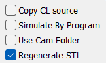
- Copy CL source cope the CL file/ NC tape to the simulation folder.
- Simulate By Program changes how the Program Group is organized in the extractor tree and how simulation job files are created (one per program).
- Use Cam Folder changes the path of simulation folder to be the same as CAM part file folder.
- Regenerate STL re-outputs STL files when the extractor runs the job again, even if STL files are already present.
VM Tolerance Selection
VM tolerances are used to calculate material removal during simulation.
- Gouge Tolerance: amount of collision authorized between tools and the finished part. This is also the cutting tolerance for computing the in-process stock.
- Collision Tolerance: motion sampling rate along the tool path, used to detect potential collisions (can be relatively large).
- Facet Tolerance: tessellation used for calculating revolution solids (milling / drilling tools, turning stock and fixtures). Value should be about 5 times smaller than the Gouge Tolerance.
- Tool Path Resolution: tolerance for approximating curved motions by short straight segments.
STL tolerances are used to output STL files from NX.
- Part Tolerance: use the same value as the Facet Tolerance entered in the VM Tolerances section (about 5 times smaller than the Gouge Tolerance).
- Stock Tolerance: set to a larger value than the Part Tolerance.
- Fixture Tolerance: set to a loose value, as safety zones are already defined in the VM model.
Save as.
Launching the Simulation Job
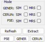
Three ICAM simulation options are available to launch from the Extractor UI:
- PSE: Launch GENER and CERUN simultaneously. Both the post-processor and the control emulator will use the same Virtual Machine model and will run either in parallel or one after the other.
- GENER: Launch the selected post-processor along with the associated Virtual Machine model.
- CERUN: Launch the selected control emulator along with the associated Virtual Machine model.
- SIM: Check to enable machine simulation.
- MRS: Check to enable material removal during simulation.
- Refresh: To retrieve or re-retrieve the CAM data.
- Extract: To output generated simulation resource.
Preference Options
More options are available under the preference options window.
To access this window, right-click the top bar of the extractor and select Preference Option.
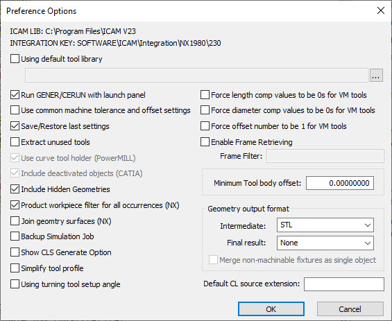
This window provides additional options which are either generic or specific to a CAM system, as shown in parentheses.
Preference options
More options are available under the preference options window. To access this window, you must right-click the extractor top bar, using the selection window, go to preference options.
This window provide additional options which are either generic or specific to a CAM system, shown in bracket.
General Settings
- Using default tool library is used when an external tool library use is preferred. This library have tools that differ from the exported tools from the CAM system.
- Run GENER/CERUN with launch panel is used when you want to have the ICAM launch UI appear. This will allow you to make some final changes to post processing or G-code emulation.
- Save/Restore last settings is used to save all your Extractor setting for the current job. Such that, if you close the Extractor, you will be able to reopen it with all the same changes you have made.
- Extract unused tools is used to extract any tools that are not used, but were created in the CAM system.
- Include hidden geometries is used to extract any geometries that are hidden in the CAM.
- Backup simulation job is used to create an additional job file as backup.
- Simplify tool profile is used to recalculate the tool profile to keep the minimum number of line segments based on the current facet tolerance.
- Using turning tool setup angle is used to set the default turning tool angle based on the tooling information.
- Force length comp values to be 0s for VM tools is used to force a value of 0 for any length compensation value inside Virtual Machine.
- Force diameter com values to be 0s for VM tools is used to force a value of 0 for any diameter compensation value inside Virtual Machine.
- Force offset number to be 1 for VM tools is used when you need to have your length and diameter offset numbers to be 1.
- Enable frame retrieving is used to retrieve the coordinate system embeded in the product, and to set it as a FRAME (coordinate system) in Virtual Machine. It's name must containt the Frame filter string.
- Minimum tool body offset: is used to offset the body of a parametric tool. A positive offset reduces the diameter of the tool body.
- Geometry output format is used to change the file format of the extracted geometry. An additional option allows you to merge non-machinable fixtures to be a single object.
- Default CL source extension: is used to tell the extractor what is the default CL or NC source extension.
Creo Setting for MFG Extractor
The following pre-settings can be used to ease the Extractor configuration procedure especially for multiple setups.
Setup Name Mapping - _[setup_ID]
'#' will be interpreted as setup number if the Mounting reference name contains "_#". (ie: ref_csys_1)
It will be used as the default mounting referene for setup#
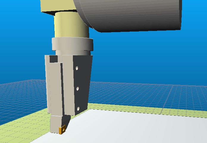
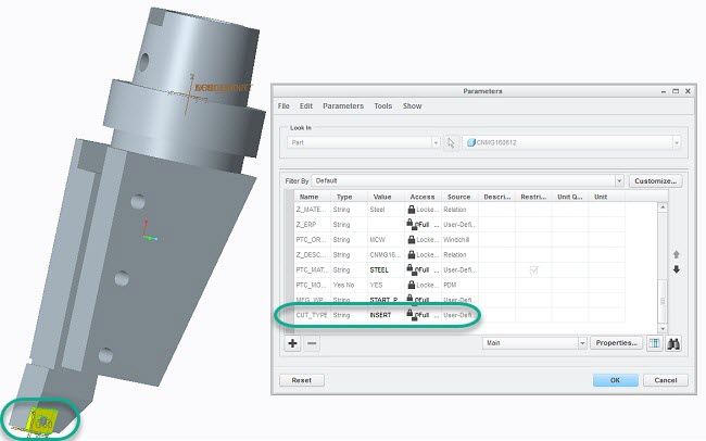
About Solid Milling Tool
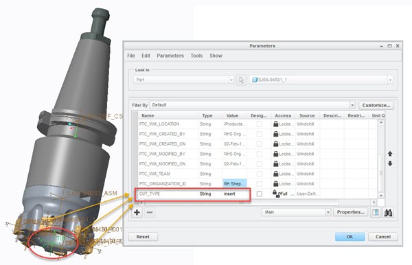
Only CUT_TYPE=insert and TIP csys is required.
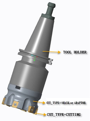
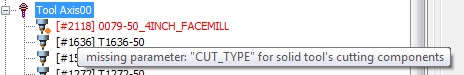
- Define parameter "CUT_TYPE" for the solid tool's cutting components
CUT_TYPE="cutter" or "cut" or "insert" or "tool"
- Optionally,you can define CUT_TYPE="shank" or "adaptor"; this conponent would be used as non0cutting part of the tool
-
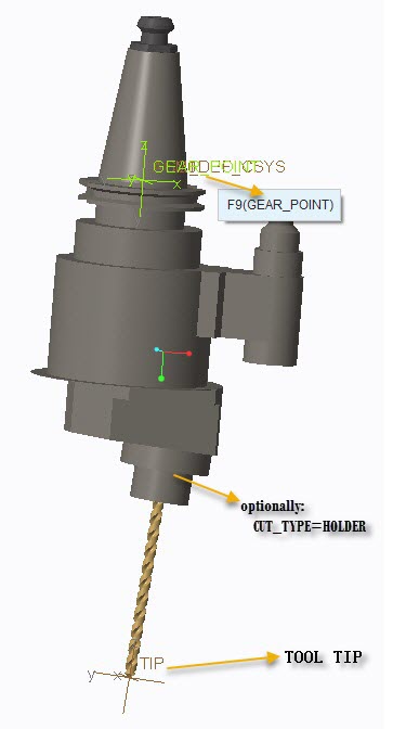
Create "TIP" CSYS as the output CSYS to control tool orientation.
Extractor will try to find TIP CSYS and GEAR_POINT. If TIP was not found, the tool will be extracted as a parametrized tool.
If there's any issue, the tool will show in red color
- GEAR_POINT for internal geared tool
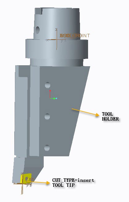
Optionally, you can define CUT_TYPE="HOLDER" to set a component to be used as a tool holder.
- Milling tool length compensation = HOLDER length + TOOL Length
About Solid Turning Tool
-
Define parameter "CUT_TYPE" for the solid tool's cutting component
CUT_TYPE="cutter" or "cut" or "insert" or "tool"
-
Create "TIP" CSYS as the output CSYS to control tool orientation
Extractor will try to find TIP CSYS. If TIP was not found, the tool will be extracted as a parametrized tool.
If there's any issue, the tool will show in red color
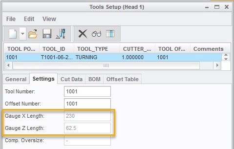
- GAUGE_X_LENGTH Á GAUGE_Z_LENGTH
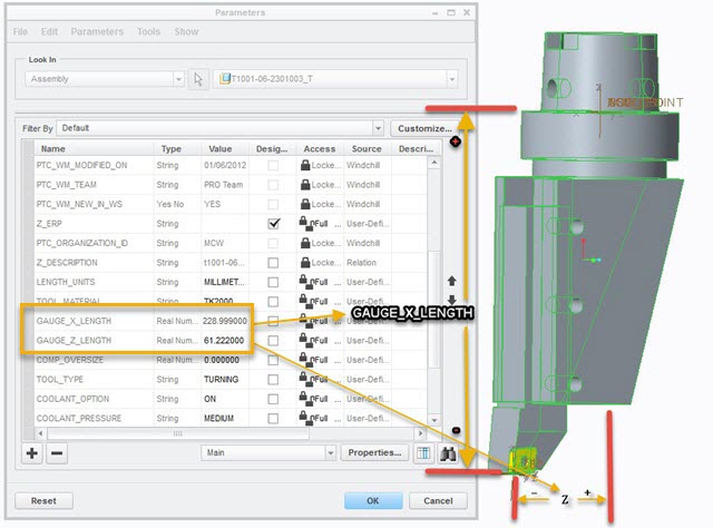
- Turning tool length compensation
*=HOLDER length + TOOL length
*=HOLDER length + GAUGE setup
- Turning tool orientation
Rotate around tool's y-axis. -90 degree if mounted to a milling-spindle with B-AXIS.