Control Emulator Customization
This section outlines the Control Emulator customization features of QUEST. The image below shows the main customization features accessible using the Navigator.
The “Code Customization” table lists all of the functions of the CNC defined in the questionnaire section. Similarly, the “Data Customization” table lists all of the defined register related data. These tables can be edited to fine-tune the behavior of the control emulator and to define your own customized codes and data.
The “Tape Editor” allows you to perform systematic search/
replace string operations on the MCD as it is read by CERUN. “Startup/Shutdown Macros” as well as “Event Macros” allow you to customize processing at predefined events during control emulation.
“Code Macros” and Data Macros” are used both to modify built-in processing of known codes and register data, as well as to support features of the CNC that are not handled by built-in control emulator functionality.
“User Function Macros” are used to develop your own macro functions that can be called by other macros in the control emulator.
The “The Dialog Editor” allows you to build dialog boxes, which can then be used by CERUN to query the NC programmer for any additional information that is necessary during control emulation.
The “File Storage” section holds read-only data files, such as controller resident subprograms, that can be accessed by CERUN.
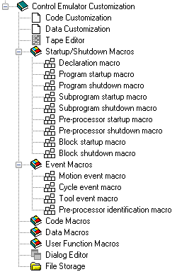
Control Emulator Customization Navigator View
Code Customization
Double-click on the “Code Customization” heading in the Navigator to open the Code Customization view in the working window. This view contains a table of all code related functions available on the machine and control, as defined in the questionnaire section of the current CE. You can edit this table to fine-tune the actions of the CE.
An image of the Code Customization main view is shown below.
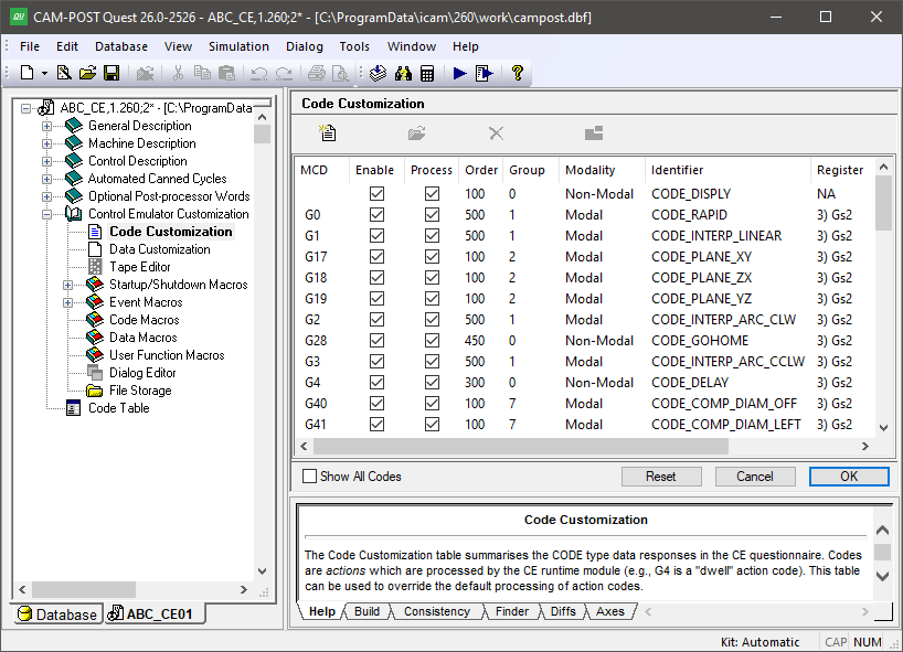
The Code Customization Facility
Modifying Code Identifiers
The following information is listed from left to right in the table for each function of the CNC that is identified by a code:
MCD: Shows the code (e.g., G1) or range of codes (e.g., G54-G59) that represent each machine or controller function that can be recognized by CERUN. The code is listed in the exact format that it is expected to be found on the MCD, with the exception of optional leading and/or trailing zeroes, decimal and sign, as defined by the register (typically the G or M) that defines the code formatting details.
Enable: If this box is selected (the default for any code defined in the questionnaire) then the code will be recognized by CERUN if it appears in the MCD or in an EXEC command. If this box is cleared, then CERUN will ignore this entry in the code customization table.
Process: If this box is selected (the default), then CERUN will process the code when it is encountered. If this box is cleared, then CERUN will remove the code from the input block and discard it without further processing.
The combination of the Process and Enable checkboxes determines how CERUN handles a code, as follows:
Enable?
Process?
Clear
-
Do not attempt to recognize this code
Set
Clear
Recognize this code, but remove it from further processing
Set
Set
Recognize and process this code
Order: Specifies the processing order of the code, in the range 1-999, with respect to other codes on the same block. CERUN processes codes from lowest to highest order when multiple codes appear on a block. If two or more codes on a block have the same order value, then they are processed from left to right. CERUN assigns a default order to codes based on industry standards, as follows:
- 100:
Settings
- 300:
Activation functions
- 400:
Cycles
- 500:
Motions
- 700:
Deactivation functions
- 900:
Stop, End, Return …
Group: Defines the group number, in the range 0-999, to which the code belongs. Group number 0 (zero) is reserved for non-modal codes. CERUN assigns a default group number to codes based on industry standards. When CERUN encounters a code during processing, it marks that code as active within the group and marks all other codes in the same group as inactive. The same group can contain both modal and non-modal codes, in which case the non-modal code overrides the modal state for the current block only. The current active code for each group can be seen in the full interface CERUN»
Code Groups window. The active code for each group can also be queried or set using the $FCEGAC and $FCESAC macro functions. Modality: Defines the modality of the code.
A “Non-Modal” code is one that applies to the current block only. Non-modal codes are always assigned to modality group 0. A dwell code (e.g., G4) is an example of a non-modal code, since the action to dwell applies to the current block only.
A “Modal” code is one whose state is remembered from one block to the next. The absolute vs. incremental codes (e.g., G90, G91) are examples of modal codes, where axes departures are interpreted in the last specified absolute or incremental mode. Interpolation codes (e.g., G0, G1…) are another example of modal codes, which effects how axes departures are interpolated.
A “Persistent” code is similar to a modal code, with the added effect that the code is reactivated on each block until canceled by another code from the same group. Persistent codes can be used in special cases where it is necessary to “fire” a code on
each block, rather than passively rely on a modal setting. More information on this topic can be found in the description of Code Macros.
Identifier: Lists the macro language identifier, in the form CODE_name, for the code identified by the MCD. The code identifier is how CERUN identifies the function that the code performs. This identifier is used in the macro processor to identify the code. For example, it can be used in EXEC commands to process a code without having to know its MCD equivalent (e.g., EXEC/CODE_SPINDLE_OFF). It can also be used in Code Macros to “catch” a code and customize how it is processed.
Register, Min, Max, *n, +n The remaining columns in the table define the code register and its value or range of values.
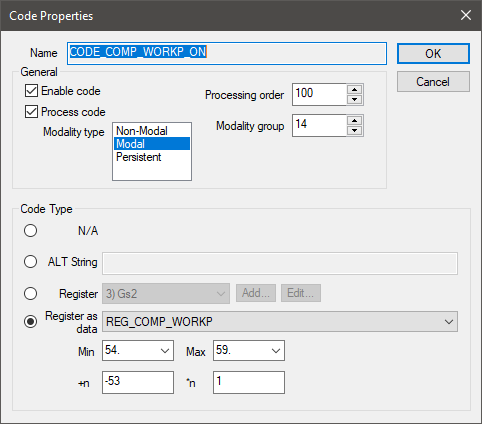
Double-click (or select and modify) a code on the table to view the different ways a code can be defined:
Select the “N/A” (meaning not applicable) radio button to define a code that has no MCD representation. A code like this cannot be recognized from the MCD, but it can be activated via the EXEC macro command.
Select the “ALT String” radio button and enter the code as a text string.
Select the “Register” radio button and choose a register from the drop-down list. Then enter the code value in the “Min” field, or the range of valid codes by specifying both a “Min” and a “Max” (i.e., minimum and maximum) value. If you write a Code Macro to perform custom processing on the code, the MCD code will be passed to the macro using the formula: $P2=(code_value*n)+n
Select the “Register as data” radio button and choose a Data identifier from the drop-down list if the code has an associated REG_name data identifier. Then enter the code value in the “Min” field, or the range of valid codes by specifying both a “Min” and a “Max” (i.e., minimum and maximum) value. The Data identifier value is calculated from the Code value using the formula: data_value=(code_value*n)+n
The difference between “Register” and “Register as data” is that the first is typically used for a simple code that activates or deactivates a function, whereas the second “as data” is used for a range of codes that both activate a function and specify “data” to that function at the same time. A common example of an “as data” type is the workpiece compensation G54-G59 range of codes, where the code both activates compensation and defines the compensation offset to use.
Select the Add button to define a new custom register if the required register format does not exist in the register drop-down list. Custom registers are identified by the string “(Custom)” in the drop-down list. Select the Edit button to modify or delete the selected custom register. Take care to not delete a custom register being used for other purposes.
Click on a column header to sort the list of codes in increasing or decreasing order based on the contents of the selected column.
Double-click on a row to bring up a Code Properties dialog that can be used to modify the selected code. You can change similar properties of multiple codes by double-clicking on a range of rows, or by selecting multiple rows and pressing the Modify button at the top of the table or the Modify menu selection on the right-mouse context menu. Any code property that is modified will be shown highlighted in the table.
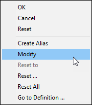
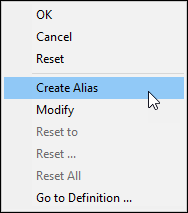
The right-mouse context menu provides various options to reset modified code fields. The “Reset to '…'” menu selection will reset the modified field selected by the mouse to the default value shown. The “Reset…” menu selection activates a small dialog with checkboxes identifying the various fields to be reset. The “Reset All” menu selection resets all fields of all selected codes to their default value. The “Reset” at the top of the context menu resets the code table back to the state it was at when you entered the section.
You can also modify a code by changing the answers to the Questionnaire concerning a particular code. Select a code and use the right-mouse context menu “Go to Definition” selection to modify the question that defined the selected code.
Creating Custom Codes
There are three different types of customized codes that can be created depending on the circumstances:
An “Alias” is a code that duplicates the functions of an existing code in the table. If there are two or more codes that provide the same functionality and you already have a code defined to handle the function, then an “alias” can be created to define an alternate code representation.
Right-mouse on the code function to be duplicated and select “Create Alias” from the context menu. This will create a copy of the code with the string “(alias)” appended to the identifier. You then use the Code Properties dialog to define the alternate representation of the code function.
One example of an alias is the use of the G54-G57 codes that overlap the G501-G599 range of workpiece compensation codes on a Siemens control. The larger range of codes should first be defined in the questionnaire (i.e., G501-G599). Then an alias of the workpiece compensation code can be created in the Code Customization table with Min/
Max values of 54 and 57 and with a “+n” offset of “–53”. Once this is done, the range of codes G54-G57 will be processed in exactly the same way as the range G501-G504. A new custom code can be created by selecting the “New” button at the top of the table. This will create a new code entry with a default name (e.g., CODE_CUSTOM_1) that you can change at any time to whatever is appropriate, provided it does not conflict with a built-in code name. You then use the Code Properties dialog to define the code, processing order and modality etcetera, as you would for any other built-in code.
If the custom code has been created simply to catch and ignore codes that have no effect on simulation, then choose CODE_IGNORE for the custom code name identifier. If desired, you can use a more meaningful code name, but you must then clear the “Process” checkbox so that the code will be ignored when read.
If a custom code does have an effect on simulation, then the “Process” checkbox must remain set and a Code Macro will have to be written to process this code when it is encountered in the MCD. The code identifier name is how the code is later recognized during Code Macro processing.
Lastly, an undefined built-in code can be used by first selecting “Show All Codes” and then enabling the appropriate undefined code. By default there will be no MCD associated with the newly enabled code since there is no information in the questionnaire section about that code. You must modify the code to define its code properties as appropriate.
Because built-in code processing functions often rely on additional data from the questionnaire, which will not be available in this case, the use of undefined codes is not recommended.
Deleting Custom Codes
Aliases and new custom codes can be deleted, by selecting one or more customized codes in the Code Customization table and either pressing the Delete key or selecting the Delete button at the top of the table.
Built-in codes cannot be deleted. To disable processing of a built-in code, simply clear the “Enable” checkbox associated with the code.
Data Customization
Double-click on the “Data Customization” heading in the Navigator to open the Data Customization view in the working window. This view contains a table of all register related functions available on the machine and control, as defined in the questionnaire section of the current CE. You can edit this table to fine-tune the actions of the CE.
An image of the Data Customization main view is shown below.
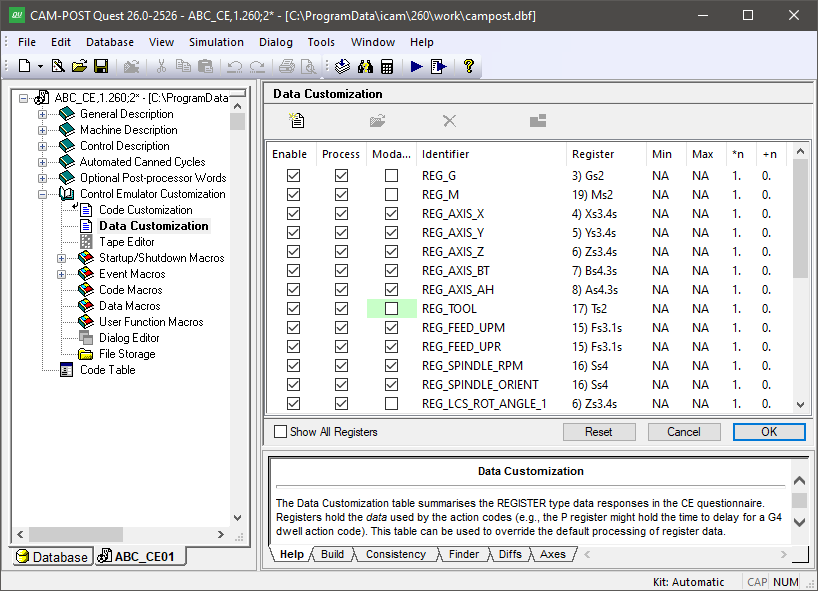
The Data Customization Facility
Unlike codes, the same register can be used for a variety of input functions. A common example is the X register that specifies the X axis position, but which can often specify a dwell time if a G4 code is present. Each of these input functions associated with the X register is assigned to a unique data identifier. CERUN uses data identifiers to access information from registers that it needs when it processes an action.
Modifying Data Identifiers
The following information is listed from left to right in the table for each function of the CNC that requires register data input:
Enable: If this box is selected (the default for any data identifier defined in the questionnaire) then the data identifier and its associated register will be recognized by CERUN if they appear in the MCD or in an EXEC command. If this box is cleared, then CERUN will output a diagnostic if the data identifier is needed during processing and the associated register will not be added to the list of allowable input words.
Process: If this box is selected (the default), then CERUN will process the data identifier as necessary. If this box is cleared, then CERUN will remove the register from the input block and discard it without further processing if it is still present after all functions have been processed on the block. Note though that CERUN will output a diagnostic if the data identifier is needed during processing.
The combination of the Process and Enable checkboxes determines how CERUN handles a register, as follows:
Enable?
Process?
Clear
-
Do not attempt to recognize this register
Set
Clear
Recognize this register, but remove it from further processing
Set
Set
Recognize and process this register
Modality: If this box is checked, the register value will be remembered and be available for use on blocks where the register does not appear. If this box is cleared, the register is non-modal and must be used on the current block. Any unused, non-modal registers on a block will be diagnosed by CERUN.
By default, CERUN currently sets all registers to non-modal despite the modality setting that may have been defined or implied in the Questionnaire, since it is our experience that the presence of an unused register on a block generally indicates a problem.
Identifier: Lists the macro language identifier, in the form DATA_name, for the register input function. The data identifier is how CERUN identifies the data that the register supplies. This identifier is used in the macro processor to identify the data. For example, it can be used in EXEC commands to supply register data without having to know its MCD equivalent (e.g., EXEC/DATA_SPINDLE_RPM,1200). It can also be used in Data Macros to “catch” a register and customize how it is processed.
Register, Min, Max, *n, +n
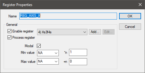
The remaining columns in the table define the register and its value or range of values. Double-click (or select and modify) a data identifier on the table to view the different ways a register can be defined:
The register that supplies the input data can be selected from the drop-down list of all registers defined in Registers section of the Questionnaire. Select the Add button to define a new custom register if the required register format does not exist in the register drop-down list. Custom registers are identified by the string “(Custom)” in the drop-down list. Select the Edit button to modify or delete the selected custom register. Take care to not delete a custom register being used for other purposes.
The “--NA--” (meaning not applicable) selection can be used to define a data identifier having no MCD representation. A register like this cannot be recognized from the MCD, but it can be activated via the EXEC macro command and $FCEADD macro functions. Using the combination of NA codes and NA registers makes it possible to construct a series of MCD commands (using EXEC) that call up custom functions and provide custom data, without interfering with normal code and data processing.
Optional minimum and/or maximum range validations can be enabled by specifying “Min” and “Max” (i.e., minimum and maximum) values. The Data identifier value is calculated from the register value using the formula: data_value=(register_value*n)+n.
Click on a column header to sort the list of data identifiers in increasing or decreasing order based on the contents of the selected column.
Double-click on a row to bring up a Register Properties dialog that can be used to modify the selected data identifier. You can change similar properties of multiple identifiers by double-clicking on a range of rows, or by selecting multiple rows and pressing the Modify button at the top of the table or the Modify menu selection on the right-mouse context menu. Any register property that is modified will be shown highlighted in the table.

The right-mouse context menu provides various options to reset modified data identifier fields. The “Reset to '…'” menu selection will reset the modified field selected by the mouse to the default value shown. The “Reset…” menu selection activates a small dialog with checkboxes identifying the various fields to be reset. The “Reset All” menu selection resets all fields of all selected data identifiers to their default value. The “Reset” at the top of the context menu resets the data table back to the state it was at when you entered the section.
You can also modify a data identifier by changing the answers to the Questionnaire concerning a particular register. Select a data identifier and use the right-mouse context menu “Go to Definition” selection to modify the register question that defined the selected data identifier.
Creating Custom Data Identifiers
There are three different types of customized data identifiers that can be created depending on the circumstances:
An “Alias” is a data identifier that duplicates the functions of an existing data identifier in the table. If there are two or more registers that provide the same functionality and you already have a data identifier defined to handle the function, then an “alias” can be created to define an alternate register representation.
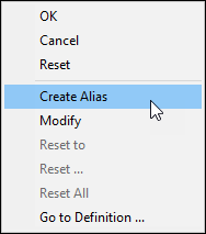
Right-mouse on the data identifier to be duplicated and select “Create Alias” from the context menu. This will create a copy of the data identifier with the string “(alias)” appended to the name. You then use the Register Properties dialog to define the alternate representation of the data.
One example of an alias would be in support of the Fanuc “standard” (vs. “calculator”) input, where a value without a decimal is processed with leading zeros omitted (e.g., X1 = 0.001 mm), but a value with a decimal is processed in the normal fashion (e.g., X1. = 1.0 mm). To support this, first define a new X axis register without a decimal and with leading zeros omitted, then create an alias of the REG_AXIS_X identifier, selecting the new X axis register in place of the old.
A new custom data identifier can be created by selecting the “New” button at the top of the table. This will create a new data entry with a default name (e.g., REG_CUSTOM_1) that you can change at any time to whatever is appropriate, provided it does not conflict with a built-in data identifier name. You then use the Register Properties dialog to define the data identifier, as you would for any other built-in data identifier.
If the custom data identifier has been created simply to catch and ignore registers that have no effect on simulation, then choose REG_IGNORE for the custom data identifier name. If desired, you can use a more meaningful data identifier name, but you must then clear the “Process” checkbox so that the register will be ignored when read.
If a custom data identifier does have an effect on simulation, then the “Process” checkbox must remain set and a Data Macro or Code Macro will have to be written to process this data identifier when it is encountered in the MCD. The data identifier name is how the data is later referenced during macro processing.
Lastly, an undefined built-in data identifier can be used by first selecting “Show All Registers” and then enabling the appropriate undefined entry. By default there will be no register associated with the newly enabled data identifier since there is no information in the questionnaire section about that data identifier. You must modify the data identifier to define its register properties as appropriate.
Because built-in processing functions often rely on additional data from the questionnaire, which will not be available in this case, the use of undefined data identifier is not recommended.
Deleting Custom Data Identifiers
Aliases and new custom data identifiers can be deleted, by selecting one or more customized entries in the Data Customization table and either pressing the Delete key or selecting the Delete button at the top of the table.
Built-in data identifiers cannot be deleted. To disable processing of a built-in data identifier, simply clear the “Enable” checkbox associated with the identifier.
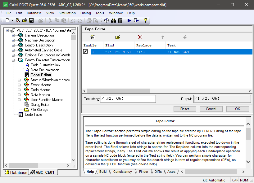
Tape Editor
The tape editor performs simple editing of the MCD as each block is read by CERUN. Editing of the tape file is the first function performed before the MCD is processed in any other way.
Tape editing is done through a set of character string replacement functions, as shown in the image below. You can perform simple character for character substitution or you may define the search strings in term of regular expressions (RE’s), as defined in the $FEDIT function (see here).
The Tape Editor Facility
Press the Add button to enter a new find/
New find/replace string pairs are added to the list below the last
selected pair. Use the up-arrow and down-arrow buttons to
reorder the string pairs (you can also reorder them with the mouse
using drag-and-drop). The order can be important, since CERUN applies
the find/
Select a string pair and press the Modify button to change one or both strings. Select a string pair and press the Delete button to remove it.
Individual find/replace strings can be enabled or disabled.
They are enabled by default when added. Clear the check box to the
left of a string pair to disable it. A disabled string pair will not
be executed by the control emulator. Individual find/
You can enter sample MCD to test out the tape editor. The final
result will be shown, as will the result after applying each of the
find/
The Finder utility includes a “Tape Editor” option to include tape editor definitions when searching through a control emulator for matching text. The Diffs utility also checks for differences in tape editor definitions when comparing control emulators.
The following table lists some tape editor Find/
Find
Replace
Description
;.*Delete tape comment starting at ; character
(.*)Remove type 2 “(…)” instruction
^/\([^0-9]\)
/1\1Replace “/” with “/1” at start of block
Startup/Shutdown Macros
Startup and Shutdown macros enable customization of CERUN processing at the start and end of certain key events.
Customization is done using the Icam Macro language (see “The Macro Language”).
Generally speaking, macros can extend or replace built-in Control Emulator functionality.
The following startup/
Macro Type
When Executed
Start of macro processing
Start and end of multi-kernel processing
Start and end of main program processing
Start and end of subprogram processing
Just before and after pre-processing
Start and end of MCD block processing
Double-click on the “Startup/
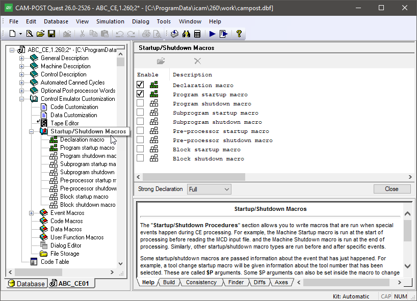
The Startup/Shutdown Macros Facility
Select a macro name and press the Modify button to create or edit it. Macros can also be opened for editing by double-clicking on the macro name in the Navigator window. To ignore a macro during CERUN processing, either uncheck the Enable box to disable it, or select the macro name and press the Delete button to remove it. The “Strong Declaration” setting is used in concert with the “Declaration Macro”.
Some startup/shutdown macros are passed information about the event that has just happened. For example, a block startup macro will include the actual block of MCD that was read. These are called $P arguments, named after the variable type that is used within the macro to access the data. Some $P arguments can also be set inside the macro to change the outcome of the event. Tables listing the $P arguments for each of the different macro types can be found below in the description of the individual macro types. The available $P arguments are also listed in the lower right Help window when you edit a macro.
Startup/Shutdown Macro Types
Declaration Macro
The declaration macro is executed at the start of macro processing. The sole purpose of a declaration macro is to provide a standard place where GLOBAL, OBJECT and FUNCTION variables can be declared and optionally assigned an initial value. No other commands are permitted in a declaration macro.
Multi-kernel processing has some important effects on the declaration macro:
For merging lathes, the same declaration macro will be run three times; once at the start of processing before the machine startup macro is run, and once each for the main and side turrets before the program startup macro is run. This is necessary because there are three separate kernels running for a merging lathe; the master kernel (#0) that handles synchronization, and one kernel each for the upper (#1) and lower (#2) turrets. All must have their macro environment initialized. The $VMCHN system variable can be used (e.g., in a CASE or IF block) if it is necessary to define different variables depending on the channel number
For composite control emulators with multiple channels, the composite master declaration macro must be used to define global variables that are to be shared between the individual component control emulators. Global variables defined in component control emulator declaration macros will be treated as object scope variables.
The declaration macro is used in combination with the “Strong Declaration” macro setting that appears at the bottom of the macro editor. There are 3 settings that control how strict the macro processor is concerning where and when variables are declared.
- OFF:
Variables can be declared when and wherever desired. The Declaration macro can be used, but it is not mandatory.
- PARTIAL:
GLOBAL, OBJECT and FUNCTION variables can only be declared in the Declaration Macro. LOCAL variables do not have to be declared before being used.
- FULL:
Same as PARTIAL, but LOCAL variables must be declared in a macro before being used.
The strong declaration setting can be changed during control emulation
(see “Tools»
The declaration macro and strong data typing features are designed to help developers create more stable macro code and catch misspellings and improper use of variables in QUEST instead of at run-time (if at all).
There are no $P variables associated with a declaration macro.
Machine Startup/Shutdown Macros
Merging lathes and composite control emulators (CE) with two or more channels have multiple instances of the CE kernel running; one kernel for each channel. The kernels in a multi-channel CE all run in parallel, and are synchronized by codes in the MCD as defined in the Questionnaire. These control emulators will have machine startup and shutdown macros (not to be confused with program startup and shutdown macros).
The machine startup macro is responsible for setting multi-kernel system variables that will affect subsequent processing (see “Multi-Kernel Control Emulator Variables”). For example, the machine startup macro can assign the MCD file or file starting point to use for each kernel.
The machine shutdown macro is run after all kernels have completed processing.
There are no $P variables associated with a machine startup and shutdown macro.
Program Startup/Shutdown Macros
The program startup and shutdown macros are executed at the beginning and end of main program processing respectively.
The program startup macro is useful for performing initialization type operations. For example, the activation of a dialog for user input, or the processing of other data files necessary for a proper simulation.
The program shutdown macro is equally useful for performing any operations you might want to have executed at the end of the program. For example, this might include the output of a diagnostic if a condition did or did not occur during processing.
Multi-kernel processing has some important effects on these macro:
For merging lathes, the same program startup macro will be run two times; once each for the main and side turrets after the machine startup macro is run. The $VMCHN system variable can be used (e.g., in a CASE or IF block) if it is necessary to perform different initialization actions depending on the channel number. The same is true for the program shutdown macro at the end of processing.
For composite control emulators with multiple channels, the composite master does not have program startup and shutdown macros (only the machine startup/
shutdown described above). However, the composite component CE’s can have a program startup macro that is run once when the component kernel is started, and can have a shutdown macro that is run once when the component kernel has completed processing.
Finally, it is possible to define a composite control emulator that has multiple component CE’s that all share the same channel. In this case, the component startup macro is run each time the component is activated (i.e., with the $FAPPLY function), and the component shutdown macro is run just before processing switches to another component.
There are no $P variables associated with program startup and shutdown macros.
Subprogram Startup/Shutdown Macros
The subprogram startup is executed just before each subprogram is called; the subprogram shutdown macro is executed just following the subprogram return.
The subprogram startup macro is useful for performing machine initialization type operations that might automatically occur when a subprogram is started. In cases where you must support controller resident subprograms, the subprogram startup macro can be used to identify the source file and offset of the controller resident subprogram either on disk or in the internal File Storage area. The $CESBST macro system variable can be set $FALSE to inhibit processing of the subprogram startup macro. By default subprogram startup macro processing is enabled if a macro is defined.
The subprogram shutdown macro is useful for performing any operations you might want to have executed at the end of the subprogram. For example, this might include the restoration of controller settings that were saved on subprogram entry. The $CESBSH macro system variable can be set $FALSE to inhibit processing of the subprogram shutdown macro. By default subprogram shut-down macro processing is enabled if a macro is defined.
The following $P variables are available with subprogram startup and shutdown macros:
$P
Description
$P1
On entry:
Type of subprogram (1:Range, 2:External)
On exit:
Leave as-is to process the subprogram
Set to 0 to ignore the subprogram call
Set to –1 to diagnose a missing subprogram
$P2
Subprogram ID string (for $P1=2)
$P3
Starting sequence number (for $P1=1)
$P4
Ending sequence number (for $P1=1)
$P5
Repeat count. Zero “0” means no repeat.
$P6
Contents of calling MCD block
$P7
Current nesting level
$P8
Current repeat count. Zero “0” if not repeating.
$P9
Filename containing subprogram (for $P1=2)
$P10
Line offset to start of subprogram (for $P1=2)
For external subprograms (i.e., $P1=2) the $P9 variable can be changed in the macro to identify the relative or absolute path and name of a file containing the subprogram. Similarly, the $P10 variable can be changed to define the line number offset to the start of the subprogram in the file identified by $P9. CERUN will attempt to locate the subprogram file based on the responses to the CALSUB section of the Questionnaire, as follows:
Subprograms attached to the main program: The subprogram will be searched for in the main program file. $P9 will identify to the main program file (e.g., “test.tap”). $P10 will contain the line number offset to the start of the subprogram or –1 if the subprogram was not found.
Subprogram all contained in a single file: $P9 will be set to a file with the same name as the main program file and with a file type of “.tps” (e.g., “test.tps”). $P10 will contain the line number offset to the start of the subprogram or –1 if the file or subprogram was not found.
Subprograms each contained in a separate file: $P9 will be set to a file with the same name as the main program file, with “_” and the subprogram ID appended and with a file type of “.tps” (e.g., “test_9001.tps”). $P10 will be 0 if the file was found, or –1 if the file was not found.
If the subprogram cannot be found using the above, CERUN will search the internal ICAMFS root directory for a file matching the REG_DEFSUB_ID subprogram definition register formatted with the subprogram ID (e.g., “O9001”).
The following is an example of a subprogram startup macro that uses the control emulator internal file storage area (see “File Storage”) to hold only those subprograms in the range O9000-O9999:
%L01=$FATOF($P2(2:)) $$ Convert ID string to number
IF/%L01.GE.9000.AND.%L01.LE.9999
   $P9=$FSWRIT('//ICAMFS/O!(\*)',%L01)
ENDOF/IF
Pre-processors have additional logic to handle the processing and searching of subprograms. Pre-processor documentation can be found in the QUEST and CERUN on-line help.
Pre-Processor Startup/Shutdown Macros
The pre-processor startup and shutdown macros will only appear if a pre-processor is in use. Pre-processors handle special requirements of popular CNC’s, such as the use of variables, functions, program branching and looping. The pre-processor is defined in the General Description / General Information section of the Questionnaire.
The pre-processor startup macro provides access to the block of MCD just prior to it being evaluated by the pre-processor. Use this macro to apply changes to the MCD that are necessary for proper pre-processor operation or to “hide” MCD from the pre-processor by temporarily removing it from the block. The $CEPPST macro system variable can be set $FALSE to inhibit processing of the pre-processor startup macro. By default pre-processor startup macro processing is enabled if a macro is defined.
The pre-processor shutdown macro provides access to the block of MCD just after it was evaluated by the pre-processor. The pre-processor performs its work by replacing variables, functions and expressions by their values. It also controls the flow of processing to handle loops and branching. The resultant MCD after pre-processing has been completed should be recognizable by CERUN using normal code and data identifier processing. The $CEPPSH macro system variable can be set $FALSE to inhibit processing of the pre-processor shutdown macro. By default pre-processor shutdown macro processing is enabled if a macro is defined.
The following $P variables are available with pre-processor startup and shutdown macros:
$P
Description
$P1
On entry:
=1
On exit:
Leave as-is to pre-process the block
Set to 0 to skip pre-processing of the block
$P2
Contents of MCD block
$P3
Block number (not the sequence number)
Block Startup/Shutdown Macros
The block startup and shutdown macros are executed at the beginning and end of processing of each block of MCD. If a pre-processor is being used, the block startup macro executes after the pre-processor shutdown macro.
The block startup macro provides access to the block of MCD just prior to it being evaluated by CERUN. Use this macro to apply any changes to the MCD that are necessary for proper CERUN processing. The $CEBKST macro system variable can be set $FALSE to inhibit processing of the block startup macro. By default block startup macro processing is enabled if a macro is defined.
The block shutdown macro provides access to the block of MCD after all other block processing is complete. Any MCD remaining on the block is data that was not recognized by CERUN. Left as-is, CERUN will output a diagnostic listing the unrecognized MCD, but you can use the block shutdown macro to remove unrecognized MCD (perhaps after an analysis) to avoid diagnostics. The $CEBKSH macro system variable can be set $FALSE to inhibit processing of the block shutdown macro. By default block shutdown macro processing is enabled if a macro is defined.
The following $P variables are available with block startup/
$P
Description
$P1
On entry:
=1
On exit:
Leave as-is to process the block
Set to 0 to skip processing of the block
$P2
Contents of MCD block
$P3
Block number (not the sequence number)
The following is an example of a one-line block startup macro that removes the = (equal sign) following any register letter:
$P2=$FEDIT($P2,'\([A-Za-z]\)=','\1')
Create or Modify Startup/Shutdown Macros
To create or modify a startup/
The lines of the macro define the actions to perform when the macro is called. These lines can contain any combination of variable assignments, logic statements, loops, function calls and control emulator commands. The macro processor executes the macro starting from the first line and working down line by line, except when the flow of processing is changed by loops and conditional or unconditional branching. Some control emulator commands and functions can cause a macro to “call” (i.e., execute) another macro. There is no practical limit on how deeply macros can be nested. Processing of the current macro picks up from where it left off after a call. See (see “The Macro Language”) for more information concerning the content of a macro.
The Macro Editor
A common macro editor interface is used for all macro editing
requirements, whether they be for startup/
The Macro Editor
The macro editor colorizes the macro code as you type it, with
comments in green, macro commands in blue, et cetera. The
colorization scheme can be changed from the “Macro Editor” tab of the
Tools»
Expression Evaluator: Use this feature to create, modify and test $FEDIT and $FMATCH macro function calls. Place the input cursor over the function name and select this function to edit an existing call. If the cursor is not on a $FEDIT or $FMATCH call, a new call will be created.
Show line numbers: Enables the display of line numbers to the left of each line.
Show whitespace markers: Shows a ‘·’ in place of blanks and an arrow in place of tabs.
Enable Word Completion: Use this feature to have the macro editor display a list of possible system variables or function names that match the text typed so far. Type any punctuation to accept the highlighted name; press the Esc key to ignore the suggestion.
Comment/Uncomment: Use this function to add comments or remove comments from a block of selected macro lines. If all macro lines in the selected range have comments, then one layer of comments will be removed from the entire block. If any or all lines in the selected range are not already commented, then a new layer of comments will be added to the entire range.
Show Source: This gives you the option to preserve the original spacing and letter case of your macro code, or to have it formatted and auto-indented each time the macro is opened in the editor. There are two styles of formatting available: The “Standard” format uses uppercase and ANSI standard logical operators (e.g., IF/X.GT.0.AND.X.LE.10) whereas the “C” format uses lowercase and C style logical operators (e.g., if/x>0&&x<=10). The choice of formatting style and whether or not to apply it when opening a macro for editing can be made from the “Macro Editor” tab of the Tools»
Preferences menu-bar selection.
Pressing the F1 function key while the cursor is placed over a system variable or function name will bring up the on-line help with more information about the selected item.
You can select your own editor (called an “external” editor) to use
instead of the default editor provided by QUEST. This is done from
the “Macro Editor” tab of the Tools»
Compiling and Saving Macros
When in the macro editor, you can use the “Compile” button to check that your code has been written correctly. Macros are always automatically compiled when you press the “OK” button after you have finished editing. The “Cancel” button ignores all changes made since you entered the macro editor for the current command. The “Reset” button ignores all changes, but keeps the macro editor active, showing the original macro code.
If a macro has compilation errors, the error diagnostics will be listed in the lower right-hand Build window. A macro must compile without errors in order for it to be used by CERUN. You can force QUEST to exit a macro that has errors, but in this case the macro will be marked as non-executable. This means that the macro cannot be used by CERUN but remains available, as written, for editing at a later date with QUEST.
The “Strong Declaration” setting defines how strict the macro compiler is concerning the timing and location of macro variable declarations (see the “Declaration Macro”).
Delete or Disable Startup/Shutdown Macros
To delete a startup/
You can also disable a macro instead of deleting it. A disabled macro remains defined in QUEST, but CERUN will not process it by default. You can also enable or disable macros at run-time for testing purposes using the CERUN debugger.
Event Macros
Event macros enable customization of CERUN processing at certain key events, as follows:
Macro Type
When Executed
On any motion
On any cycle motion
At a tool change
When a diagnostic occurs
Responds to pre-processor queries
Double-click on the “Event Macro” heading in the Navigator to open the Event Macro view in the working window as shown below. Select a macro name and press the Modify button to create or edit it. Event macros can also be opened for editing by double-clicking on the macro name in the Navigator window. To ignore an event macro during CERUN processing, either uncheck the Enable box to disable it, or select the macro name and press the Delete button to remove it.
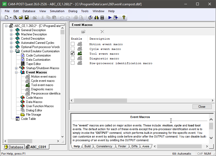
The Event Macros Facility
All event macros are passed information about the event that is about to happen. This information is passed in the form of $P arguments, named after the variable type that is used within the macro to access the data. Some $P arguments can also be set inside the macro to change the outcome of the event. Tables listing the $P arguments for each of the different macro types can be found below. The available $P arguments are also listed in the lower right Help window when you edit a macro.
Event macros are very similar to the startup/
actions before eventOUTPUTactions after event
The actions before and/or after the OUTPUT command are optional, as is the use of the OUTPUT command itself (allowing you to replace built-in processing with your own macro logic).
The designers of Control Emulator chose to use startup and shutdown macros for some types of events and event macros for other events. For events that are separated by a potentially large gulf in time (e.g., program startup and program shutdown), it didn’t seem proper to have a “Program Event” macro that would remain active throughout the entire program, therefore separate Startup and Shutdown macros were implemented. For those events where macro intervention is likely to be brief, the designers chose to use Event macros.
Event Macro Types
Motion Event Macros
The Motion Event macro is executed each time a block of MCD contains a motion. A motion event macro can be used to suppress motions under certain conditions and to process additional motions if necessary. The $MTNMAC macro system variable can be set $FALSE to inhibit processing of the motion event macro. By default motion event macro processing is enabled if a macro is defined.
The motion processing of the control emulator occurs when the OUTPUT command of the motion event macro is executed. Commands placed in the macro prior to the OUTPUT command will be processed before the motion; commands placed after the OUTPUT command will be processed after the motion has completed.
The following $P variables are available with a motion event macro:
$P
Description
$P1
Type of motion:
1: Circular interpolation (e.g., G2, G3)
2: Threading (e.g., G33, G34)
4: Rapid positioning (e.g., G0)
5: Linear interpolation (e.g., G1)
$P2
End position
$P3
Circle center (for $P1=1)
$P4
Circle plane vector (for $P1=1)
$P5
3D circle midpoint (for $P1=1)
$P6
Circle direction (for $P1=1)
1: clockwise (e.g., G2)
2: counterclockwise (e.g., G3)
$P7
Circle plane (for $P1=1)
0: 3D circle (i.e., through point)
1: 2D circle in XYplane
2: 2D circle in ZX plane
3: 2D circle in YZ plane
$P8
Motion flags
The $P2 end position is defined as a sequence of 6 elements representing up to 6 axes of simultaneous motion. The $P8 motion flags is also a sequence of 6 elements, indicating with a numeric value “1” if a motion was coded on the current block for that axis. A value of “0” identifies an axis whose value has not been changed and whose $P2 value is the result of a previous motion. The $AXES system variable identifies the order and type of axes defined by the $P2 variable.
The $P1 variable is set to “1” for circular motions. The $P3, $P4 and $P5 variables are all sequences of 3 elements defining the machine XYZ circle center, vector normal to the circle plane and circle midpoint (for 3D arcs). $P6 defines the direction of interpolation and $P7 defines the plane of interpolation. These variables are all set to $NULL if the motion type is not circular.
Cycle Event Macros
The Cycle Event macro is executed each time a block of MCD contains a canned cycle instruction. As with a motion event macro, a cycle event macro can be used to suppress cycle motions under certain conditions and to process additional motions if necessary before and/or after the cycle. The $CYCMAC macro system variable can be set $FALSE to inhibit processing of the cycle event macro. By default cycle event macro processing is enabled if a macro is defined.
A cycle event macro will be executed before a motion event macro if both are defined. The cycle processing of the control emulator occurs when the OUTPUT command of the cycle event macro is executed. A motion event macro will be executed for every motion that occurs within the cycle while the cycle OUTPUT command is being processed.
The following $P variables are available with a cycle event macro:
$P
Description
$P1
Cycle CODE identifier (e.g., CODE_CYCLE_DRILL)
$P2
Reference height (for activator cycles)
$P3
Clearance height at start of cycle
$P4
Retract height at end of cycle
$P5
Depth of cycle
$P6
BORE-BACK bottom clearance position
Tool Event Macros
The Tool Event macro is executed each time a block of MCD contains a tool preselection or tool change instruction. The tool event macro is also called for exchangeable head unit preselection and change operations. A tool event macro can be used, for example, to duplicate the workpiece-to-home and home-to-workpiece positioning sequences of the machine.
The following $P variables are available with a tool event macro:
$P
Description
$P1
Event type:
1: Pre-selection
2: Load
$P2
Device type:
0: Tool
1: Head
$P3
Tool or Head ID
Diagnostic Event Macro
A diagnostic macro is executed whenever a diagnostic (message, warning, error, fatal) is processed. The macro will be called even if the diagnostic is disabled, however it will not be called if all diagnostic processing is disabled via the $ERRMSG system variable. The macro is called before the diagnostic is output and counted in the statistics. The diagnostic message can be modified, deleted or additional diagnostics inserted using the diagnostic macro feature.
Diagnostic macros have the following $P variables:
$P
Description
$P1
Flag (0:Disabled/
Delete, 1:Enabled/ Output) $P2
Diagnostic number
$P3
Severity number
$P4
Diagnostic occurrence
$P5
Diagnostic message
$P1 controls the diagnostic macro. On entry, $P1 represent the enabled status of the diagnostic number. When the macro terminates, the value of $P1 is checked by the control emulator to determine if the diagnostic should actually be output. Setting $P1 to zero will cause the diagnostic to be discarded. Setting $P1 to any other value will cause the diagnostic to be output to the UI, listing and also counted in the statistics.
$P2 is a real number representing the diagnostic number as defined in the cer270.err file (see “Error File”). $P2 is can be modified in order to output other diagnostics.
$P3 is the diagnostic severity number as defined in the cer270.err file. The severity can be changed by modifying the value of $P3. This is the equivalent of calling the $FERSEV function.
$P4 is a real number representing the number of times the diagnostic identified by $P2 has been generated. The first occurrence of a specific diagnostic will have $P4 set to 1 on entering the macro. Subsequent occurrences will increment $P4. This variable is read-only.
$P5 is a string containing the formatted diagnostic message text. This variable can be altered in order to customize the message that will be output.
You can generate additional diagnostic messages by coding an OUTPUT command. This command causes the diagnostic message, as identified by the $P variables, to be output. The $P variables can then be changed, and OUTPUT called again.
Diagnostic macros can modify user global and object variables as well as macro system variables. Diagnostic macros can also use any macro commands excluding those that process MCD.
The diagnostic macro can be toggled on or off by use of the $DIAGMAC macro system variable ($TRUE or $FALSE).
Pre-Processor Identification Macros
The pre-processor identification macros will only appear if a pre-processor is in use. Pre-processors handle special requirements of popular CNC’s, such as the use of variables, functions, program branching and looping. The pre-processor is defined in the General Description / General Information section of the Questionnaire.
The pre-processor identification macro is called by the pre-processor whenever it cannot recognize a function or variable in the current MCD block. The $CEPPID macro system variable can be set
$FALSE to inhibit processing of the pre-processor identification macro (which means of course that unrecognized functions and variables will be diagnosed). By default pre-processor identification macro processing is enabled if a macro is defined.
The following $P variables are available with pre-processor identification macro:
$P
Description
$P1
On entry:
=0
On exit:
-1: quietly ignore the unrecognized MCD
0: diagnose and ignore the unrecognized MCD
1: re-evaluate the modified MCD in $P2
2: accept unrecognized MCD and continue
$P2
Unrecognized function or variable
$P3
Value being assigned to $P2 if on left side of assignment. $NULL otherwise.
The default action of the preprocessor identification macro is to discard the unrecognized MCD and signal an error. Set $P1 to –1 to quietly discard the unrecognized MCD. If the unrecognized function or variable is part of an expression, it will be replaced by the value 0 (zero) instead of discarding it. This is also how unrecognized functions and variables are handled when a pre-processor identification macro is not being used.
If the pre-processor macro is able to identify the unrecognized function or variable, then $P2 must be set to the as-evaluated result and, most importantly, $P1 must be set to 1 (one) to tell the pre-processor to use the new $P2 value in replacement for whatever it was that was not recognized in the first place. For example:
CASE/$P2
   WHEN/'#5001'
      $P2=$XM
   WHEN/'#5002'
      $P2=$YM
      …
WHEN/OTHERS
   TERMAC
ENDOF/CASE
$P1=1
An error will be diagnosed if $P1 is set to 1 but $P2 is left unchanged.
If the text in $P2 is normally part of a larger construct (e.g., the “TR” enumerated type on a Siemens controller), then $P1 can be set to 2 to tell the pre-processor to continue evaluating the expression using the unrecognized text as-is.
Finally, if $P2 represents an unknown variable that appears on the left hand side of an assignment, then $P3 will contain the value of the expression on the right hand side of the assignment. $P3 will be $NULL if the unrecognized variable or function is not being assigned a value.
Create or Modify Event Macros
To create or modify an event macro, double click on the macro name in the Navigator. Alternately, you can open the Event Macros section header in the Navigator, select one of the event macros listed in the upper right main working window (see image above) and then press the Modify button at the top of the window (or double-click on a listed macro). When a macro is created or modified, the macro editor occupies the main work space.
The lines of the macro define the actions to perform when the macro is called. These lines can contain any combination of variable assignments, logic statements, loops, function calls and control emulator commands. The macro processor executes the macro starting from the first line and working down line by line, except when the flow of processing is changed by loops and conditional or unconditional branching. Some control emulator commands and functions can cause a macro to “call” (i.e., execute) another macro. There is no practical limit on how deeply macros can be nested. Processing of the current macro picks up from where it left off after a call. See see “The Macro Language” for more information concerning the content of a macro.
The Event Macro Editor
The Event Macro editor is identical to the Startup/
Delete or Disable Event Macros
To delete an event macro, open the Event Macros section header in the Navigator, select one of the event macros listed in the upper right main working window (see image above) and then press the Delete button at the top of the window (or the Delete key). A deleted macro cannot be recovered, so be careful when deleting.
You can also disable an event macro instead of deleting it. A disabled macro remains defined in QUEST, but CERUN will not process it by default. You can also enable or disable macros at run-time for testing purposes using the CERUN debugger.
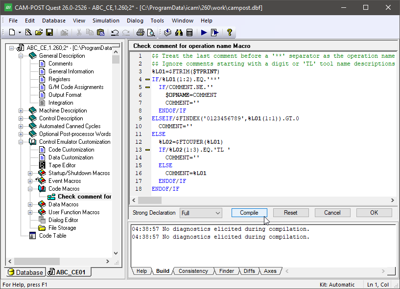
Code Macros
This section provides the capability to define processing associated with custom CNC codes (i.e., codes that are not supported by Control Emulator), or to replace or modify built-in processing of codes that are known to Control Emulator. This is done by creating macros that will “match” codes read from the MCD. These macros can in turn do whatever processing is necessary for the matched code.
Double-click on the “Code Macros” heading in the Navigator to open the Code Macros view in the working window. This view shows all code macros defined for the control emulator. An image of the Code Macros main view is shown below.
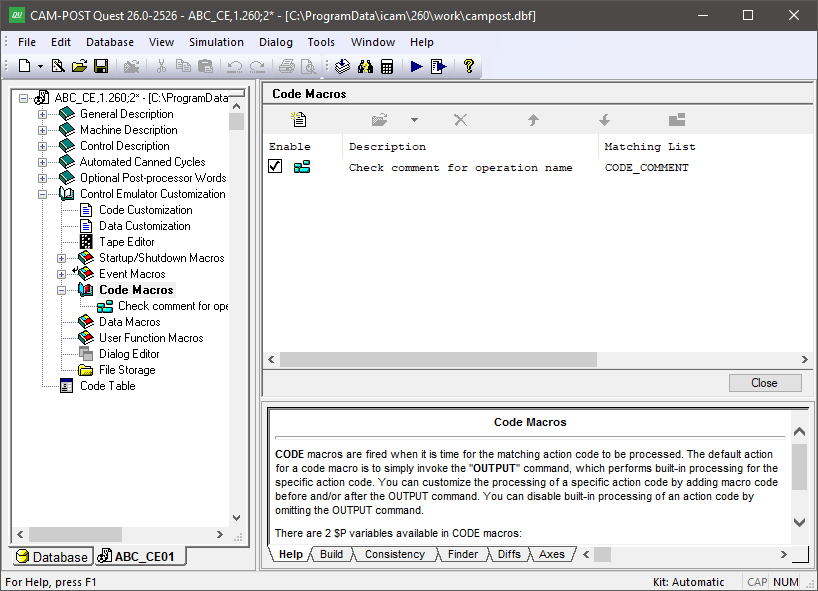
The Code Macros Facility
The Navigator also lists all code macros that have been defined for the control emulator. Code macros are listed by their descriptive name, which you can enter when creating the macro or by modifying the “matching information” of a macro (described in the Create Code Macros section below). The default name of a macro is constructed from the list of code identifiers that the code macro matches. You can open a macro for editing by double-clicking on the macro definition in the Navigator or in the working window, or by first selecting a macro in the working window and then pressing the “Modify” button.
Create Code Macros
Press the Add button to create a new code macro. A Code Macro Properties dialog window will appear, which is used to define the conditions that will cause the code macro to be matched by CERUN when processing the MCD. An image of the Code Macro Properties dialog is shown below (the code matching conditions are taken from “Macro Example #2” in the annex).
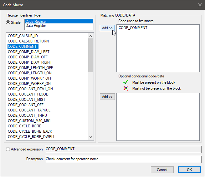
The Code Macro Properties Dialog
The first step when adding a code macro is to define the code or codes that must be present on the MCD block in order to execute the macro. You do this by first selecting “Code Identifier” in the upper left window of the dialog to see a list of all known code identifiers, then selecting one or more code identifier that this macro is being written to match and finally by pressing the upper Add button to add the code identifiers to the list of codes used to match the macro. You can add to the list of matching codes by repeatedly selecting code identifiers and pressing the Add button. You remove a code identifier from the list of matching codes by selecting it and pressing the Delete key (on the keyboard). If multiple matching codes are defined, the default condition is to execute the code macro if any one of the matching codes is present on the block. If multiple matching codes are present on the block, then the code macro will be executed for each matching code in turn in their order of execution (i.e., as defined by the code “order” setting, or left to right on the MCD block for codes with the same order setting).
You can optionally define other code identifiers and/or data
identifiers that either must be present on the block of MCD or that
must not be present on the block of MCD, in order to execute the
macro. You do this by first selecting “Code Identifier” or
“Data Identifier” in the upper left window of the dialog to
see a list of all known code or data identifiers, then selecting one
or more code or data identifiers from the list and finally by
pressing the lower Add button to add the identifiers to the list
of conditional identifiers. Use the checkbox to the left of each
conditional code or data identifier to toggle between “must be
present” and “must not be present” conditions. If
multiple conditional code/
If the default matching conditions are not suitable, then the “Advanced” radio button can be selected and the matching condition can be entered by hand. The matching condition is entered as a Boolean macro expression consisting solely of code and data identifier names, the .AND. and .OR. logical operators (or C style && and || operators) and parentheses if it is necessary to override the default operator precedence of AND before OR.
When a new code macro is added, the macro editor occupies the main
work space. By default, a new code macro consists of a single
OUTPUT macro command. The OUTPUT macro command tells CERUN to
perform the built-in processing associated with whatever code it was
that matched the macro. Macro code placed in the lines before the
OUTPUT command will be executed by CERUN before built-in processing.
Macro commands placed after the OUTPUT command will be executed by
CERUN after built-in processing. You can omit the OUTPUT command to
replace any built-in processing by your own macro code. An empty
macro is one that will “do nothing” when the matching code/
A code macro can contain EXEC commands that cause additional codes to be executed or MCD to be evaluated by CERUN. This is the primary form of customization used by CERUN. Codes and/or MCD that is processed by an EXEC command is subject to code macro matching in the same way that as the original MCD. This means that code macros containing EXEC commands can cause other code macros to be “called”. There is no practical limit on how deeply code macros can be nested, but no code macro that is already active can be a candidate for further code macro matching. This means that it is not possible to write recursive code macros.
The following $P variables are available with code macros:
$P
Description
$P1
Code identifier
$P2
Code value
The $P1 variable initially contains the matching code identifier. This is the code that will “fire” when an OUTPUT command is coded. The $P1 variable can be changed in the macro to any valid code identifier before calling OUTPUT. A code macro can execute multiple codes by repeatedly setting $P1 to a code value and then calling OUTPUT.
The $P2 variable contains either the corresponding code identifier numeric value if it can be determined, or the text of the code itself. The numeric code value is calculated using the formula: $P2=(code*n)+n, where the “*n” and “+n” values are defined in the Code Customization table.
The Code Macro Editor
The Code Macro editor is identical to the Startup/
Code Macros Match Order
You can have more than one code macro with the same matching conditions. When this is the case, CERUN will try to find a match starting with the first one in the list. The order is not important when each code macro has completely different matching conditions, but it becomes much more important when this is not the case.
To change the order of a macro within the list (see this image), select the macro and then use the up-arrow and down-arrow buttons to move it. You can also use the mouse to change the order by first selecting the macro and using drag-and-drop.
When multiple code macros can be matched from the current MCD, the first matching code macro in the list that is not already active is executed. Once a code macro has been matched and is being executed, it is no longer a candidate for subsequent matching. Once the code macro has completed, then it again becomes available for matching. An OUTPUT command in a code macro will cause the next matching code macro in the list to be executed and so on until no other matching macros exist. A code that is not matched by a code macro is then processed using built-in logic if any, or diagnosed if the code is not recognized.
Modify Code Macro Matching Conditions
To modify a code macro, open the Code Macros section header in the Navigator, select one of the code macros listed in the upper right main working window and then press the Modify button at the top of the window. There are two forms of modification:
Modify matching info: This opens the Code Macro Properties dialog to allow editing of the matching condition and/or the descriptive name of the code macro.
Modify macro: This opens the macro editor to allow editing of the code macro contents
Delete or Disable Code Macros
To delete a code macro, open the Code Macros section header in the Navigator, select one of the code macros listed in the upper right main working window and then press the Delete button at the top of the window (or the Delete key). A deleted macro cannot be recovered, so be careful when deleting.
You can also disable a code macro instead of deleting it. A disabled code macro remains defined in QUEST, but CERUN will not process it by default. You can also enable or disable macros at run-time for testing purposes using the CERUN debugger.
Data Macros
A Data identifier defines the input register format for a corresponding Code identifier. For example, a REG_SPINDLE_RPM identifier defines the speed of spindle rotation to use when a CODE_SPINDL_CLW code identifier is being processed. Data Macros can be written to customize the processing of Data identifiers in much the same way that Code macros can be written to customize the processing of Code identifiers. A Code macro defines how the code is processed; a Data macro defines how the value of the data identifier is calculated.
Double-click on the “Data Macros” heading in the Navigator to open the Data Macros view in the working window. This view shows all data macros defined for the control emulator. An image of the Data Macros main view is shown below.
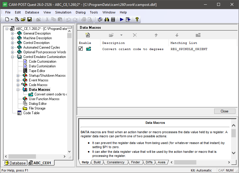
The Data Macros Facility
The Navigator also lists all data macros that have been defined for the control emulator. Data macros are listed by their descriptive name, which you can enter when creating the macro or by modifying the “matching information” of a macro (described in the Create Data Macros section below). The default name of a macro is constructed from the list of data identifiers that the data macro matches. You can open a macro for editing by double-clicking on the macro definition in the Navigator or in the working window, or by first selecting a macro in the working window and then pressing the “Modify” button.
Create Data Macros
Press the Add button to create a new data macro. A Data Macro Properties dialog window will appear, which is used to define the data identifiers that will cause the data macro to be matched by CERUN. An image of the Data Macro Properties dialog is shown below.
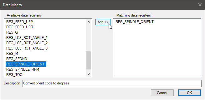
The Data Macro Properties Dialog
The first step when adding a data macro is to define the data identifiers that will match the macro. You do this by first selecting one or more identifiers from the list of all known data identifiers and then by pressing the Add button to add them to the list of data identifiers that match the macro. You can add to the list of matching data identifiers by repeatedly selecting data identifiers and pressing the Add button. You remove a data identifier from the list of matching identifiers by selecting it and pressing the Delete key. If multiple data identifiers are defined, then the macro will be used when processing any of the listed data identifiers.
When a new data macro is added, the macro editor occupies the main work space. By default, an empty data macro is created. The main purpose of a data macro is to modify the calculated data identifier value, which is done by changing the value of the $P2 variable (see table below). A data macro can contain EXEC commands that cause additional codes to be executed or MCD to be evaluated by CERUN. Careful consideration must be taken to ensure that the EXEC command does not interfere with the current code processing that resulted in the data macro being called. Generally speaking, EXEC commands should not be used in a data macro. The OUTPUT command must not be used in a data macro since the purpose of a data macro is to return data to a calling function and not to generate output.
The following $P variables are available with data macros:
$P
Description
$P1
On entry:
=1
On exit:
Leave as-is to return $P2 value
Set to 0 to not return a value
$P2
Data value
$P3
Data identifier
$P4
Value type:
1: Absolute
2: Incremental
$P5
Register “order” number, or zero (0) if not a register
The $P1 variable can be set to zero on return to tell CERUN that there has been an error trying to evaluate the data identifier. CERUN will then typically output a diagnostic saying that information is missing for whatever code function was being processed.
The $P2 variable contains the value of the data identifier, which is calculated using the formula: $P2=(register*n)+n, where the “*n” and “+n” values are defined in the Data Customization table.
The $P3 variable contains the matching data identifier, which can be useful when a data macro has multiple matching data identifiers.
The $P4 variable indicates for machine axes values whether the $P2 value will be processed as an absolute one ($P4=1), or as an incremental one ($P4=2). $P4 will be set on input to the expected type based on the axis letter address for controllers that use different letter addresses for absolute and incremental data (e.g., XYZ vs. UVW), or based on the current CODE_POSITION_ABSOLUTE or CODE_POSITION_INCREMENTAL settings (e.g., G90 vs. G91). The $P4 variable can be changed on return to override how CERUN evaluates the value.
The $P5 variable will contain the register “order” number if the data identifier is associated with a register. Otherwise, $P5 will be zero (0).
The Data Macro Editor
The Data Macro editor is identical to the Startup/
Data Macros Match Order
You can have more than one data macro with the same matching identifier. When this is the case, CERUN will execute each matching data macro in the order listed. The order is not important when each data macro has different matching identifiers, but it becomes much more important when this is not the case.
To change the order of a macro within the list (see image above), select the macro and then use the up-arrow and down-arrow buttons to move it. You can also use the mouse to change the order by first selecting the macro and using drag-and-drop.
Modify Data Macro Matching Conditions
To modify a data macro, open the Data Macros section header in the Navigator, select one of the data macros listed in the upper right main working window and then press the Modify button at the top of the window. There are two forms of modification:
Modify matching info: This opens the Data Macro Properties dialog to allow editing of the matching data identifiers or the descriptive name of the data macro.
Modify macro: This opens the macro editor to allow editing of the data macro contents
Delete or Disable Data Macros
To delete a data macro, open the Data Macros section header in the Navigator, select one of the data macros listed in the upper right main working window and then press the Delete button at the top of the window (or the Delete key). A deleted macro cannot be recovered, so be careful when deleting. You can also disable a data macro instead of deleting it. A disabled data macro remains defined in QUEST, but CERUN will not process it by default. You can also enable or disable macros at run-time for testing purposes using the CERUN debugger.
User Function Macros
This section allows you to define your own macro functions, which can be called by other macros in the control emulator. To do this, create macros that specify a function name, its parameters, and optionally a return type. Functions defined here are automatically available to other macros and functions in the control emulator — no separate declaration is needed. This section does not cover the macro language itself; see :ref:“The Macro Language”<macro_language> for details on how to write macros.
Double-click on the “User Function Macros” selection in the Navigator to open the main macro view in the working window. This view shows all user function macros. An image of the User Function Macros main view is shown below.
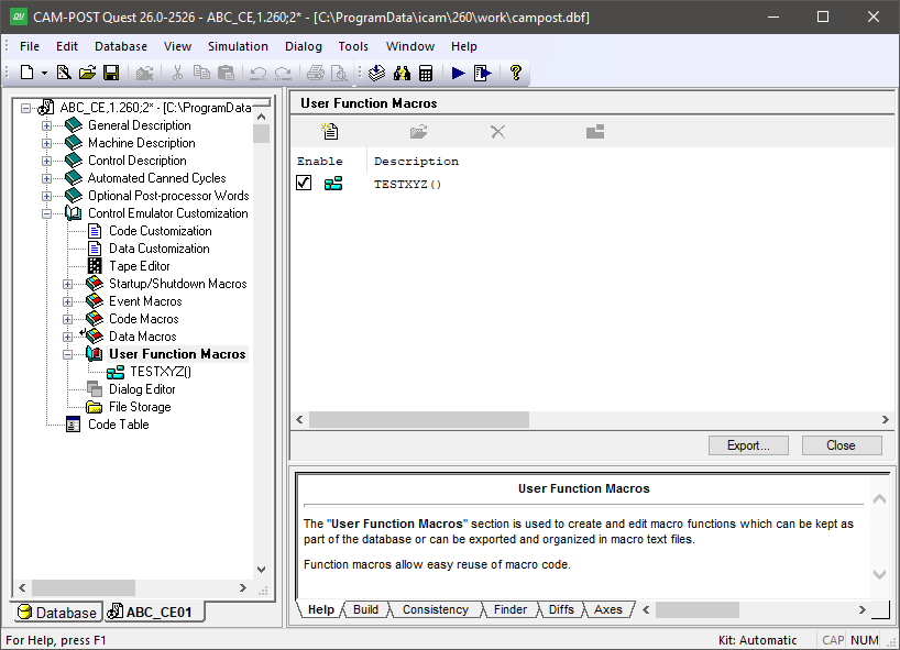
The User Function Macros Facility
The navigator lists function macros alphabetically by name. You can open a function macro for editing by double-clicking on the macro definition in the navigator or in the working window. You can also edit a function macro by selecting it in the working window and then pressing the Modify button. Only a single function macro can be edited at a time.
Create User Function Macro
Press the Add button to add a new function macro. You will be asked to enter a function name, which must start with an alphabetic character and consist of only letters, digits and the underscore character. The name cannot be longer than 32 characters. It also cannot be the same as any function name that is already defined.
When a new function macro is added, the macro editor occupies the main work space. The first line of the macro will contain the string “MACRO/” followed by the function macro name and open and closing parentheses ( ). This first line of the macro is called a Syntax Definition Line, or just SDL for short. The SDL defines the name of the function, its parameters and optionally the function return value type. More details of function macro SDLs can be found in “User Function Macros”.
The remaining lines of the macro (i.e., the body) define the actions to perform when the function macro is called. The macro processor first copies the variables and/or constants used by the caller into the parameter values of the function macro. It then processes the body of the function macro. When the macro completes, either by processing a TERMAC or ENDMAC command, the function macro then returns a value to the caller. This value must be set in the body of the function macro before returning, by setting a variable having the same name as the function macro name.
User function macros are ordered alphabetically, with no duplicates allowed, so there is no concept of ordering macros to affect how they are matched, as is done for code and data macros (i.e., the up and down arrow controls are disabled in the macro editor view).
The User Function Macro Editor
The User Function Macro editor is identical to the Startup/
Macro function names can be changed (i.e., renamed) simply by editing the macro function, modifying the function name in the SDL, and compiling and/or exiting.
Delete or Disable User Function Macros
To delete a user function macro, open the User Function Macros section header in the Navigator, select one of the user function macros listed in the upper right main working window and then press the Delete button at the top of the window (or the Delete key). A deleted macro cannot be recovered, so be careful when deleting.
User function macros cannot be disabled.
Export User Function Macros
Press the Export button to select the function macros to be written in ASCII format to the selected file. Each macro is followed by an ENDMAC command in the generated file.
There is no corresponding Import function.
The Dialog Editor
The Dialog editor is used to build dialog boxes, which are then used in CERUN to query the user for any information that is necessary during control emulation. You can create many different dialogs, each with a unique name, which are then activated using the $FDIALOG macro function call.
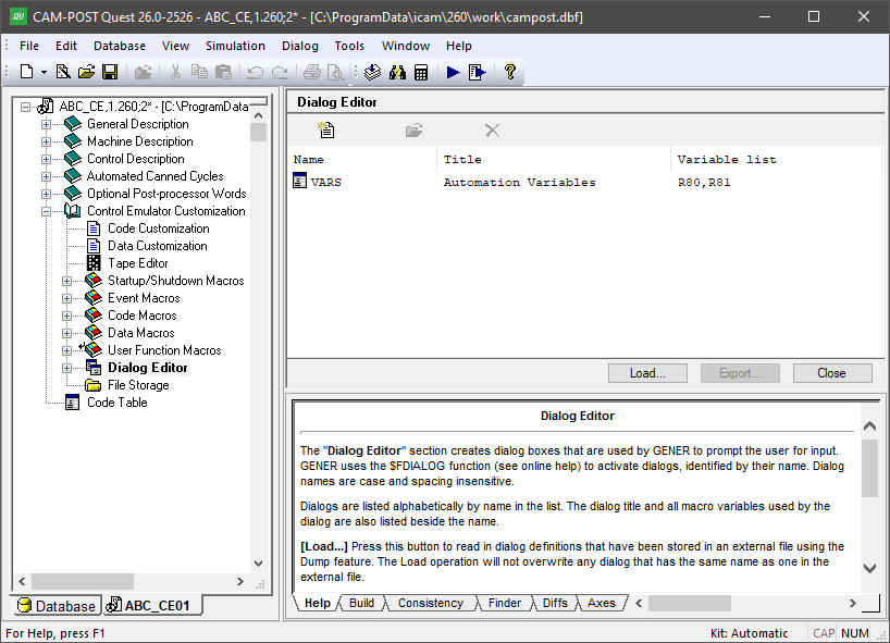
The Dialog Editor Facility
Press the Add button to create a new dialog. You will be prompted for the dialog’s name, which is how the dialog will be identified in the $FDIALOG function call. Spacing and letter-case are not significant in dialog names. Dialogs are listed alphabetically by name. For each dialog, the listing includes its name, the caption title that will appear at the top of the dialog window and a list of all macro variables referenced by the dialog (dialogs operate by getting and setting macro variables). Note that a single dialog containing all user input requirements is generally preferable to the user (if properly constructed) than a series of smaller dialogs.
Select an existing dialog from the list and press the Modify button (or double click on a list entry) to make changes to an existing dialog. Select one or more dialogs and press the Delete button to remove them from the control emulator. This function cannot be undone.
There are also Load and Dump buttons that can be used to read and write dialog definitions from/to external files. Use this feature to copy dialogs from one control emulator to another, or to create “external” dialogs that can be accessed by any control emulator. We recommend that you do not edit dialog definitions by hand.
The Finder utility includes a “Dialogs” option to include dialog definitions when searching through a control emulator for matching text. The Diffs utility also checks for differences in dialogs when comparing control emulators. Dialogs are listed in XML format in the Finder and Diffs windows.
The Dialog Template Editor
When a dialog is first created it consists of a single window frame and two buttons: OK and Cancel. The image below shows an example of the dialog template editor.
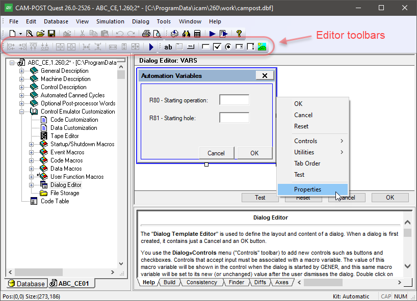
The Dialog Template Editor
The window frame can be resized by selecting it and then dragging (with the left-mouse button held down) one of the three resize points on the exterior of the window. You can also double-click on the window to edit the windows “Properties”, which include: its caption title, name, size in screen pixels and margin (like the margins of a printed page). Similarly, the OK or Cancel button can be selected and resized using the mouse, or double-clicked on to edit its button properties. This behavior is true for all dialog “controls”.
Dialogs can contain a number of different types of window controls,
which can be selected from the Controls toolbar or from the
Dialog»
Text: Use this control to add text to your dialog. Properties include the position and the text itself. You can use line breaks in the text input field to show multi-line text in the dialog. The text control is automatically sized to the required text width and height.
Frame: Use this control to visually group related dialog controls. Properties include the text label that appears at the top-left corner of the frame and the position and size of the frame.
Button: Use this control to create buttons, such as the OK and Cancel buttons. Properties include the text label that appears inside the button, the type of button and the position and size of the button. Buttons with an “OK” type cause the dialog to close when they are pressed, returning the button label text (e.g., “OK”) as the return value to the $FDIALOG function and all dialog macro variables set as shown in the dialog. Buttons with a “Cancel” type cause the dialog to close, returning the button label text (e.g., “Cancel”) and leaving all dialog macro variables unchanged (but initialized if necessary). Buttons with a “Reset” type don’t close the dialog; instead, they reset all controls to their initial state. Buttons with a “Call Dialog” type activate the specified dialog when pressed. A dialog called in this manner must reside in the same control emulator or external file as its caller. You can choose to display (and return) any text you want for a button.
Edit box: Use this control to create a field that will optionally accept user-typed input. Properties include the default value for the field, its associated macro variable, the position and size of the edit box field, an “editable” flag indicating if the field can be changed by the user and a “numeric only” flag with optional minimum/
maximum range limits to force user input to be numeric. When the $FDIALOG function is called, the edit box field will initially be set to the macro variable value. The edit box field will instead initially be set to the default value if the macro variable does not exist, or is $NULL, or is an empty string. The macro variable will be set to the contents of the edit box field when an OK type button is pressed. Check box: Use this control to accept logical True/
False type input from the user. Properties include an optional text label that will appear to the right of the check box, the default set/ clear state for the check box, its associated macro variable and the position of the check box control. When the $FDIALOG function is called, the check box field will initially be set if: the variable is logical and is true; or the variable is numeric and non-zero; or the variable is text and is $TRUE. The check box field will initially be cleared if: the variable is logical and is false; or the variable is numeric and zero; or the variable is text and is $FALSE. The check box field will instead initially be set to the default value if the macro variable does not match any of the preceding, or does not exist, or is $NULL. The macro variable will be set to one of the true/ false conditions, based on the macro variable type, when an OK type button is pressed. Radio button: Use this control to present the user with a series of exclusive choices. Properties include an optional text label that will appear to the right of the radio-button, an optional alternate return value, an initial state setting, its associated macro variable and the position of the radio-button control. When a radio button is selected, the macro variable will be set by default to the label text. You can choose to return something different for the variable by specifying an alternate return value (e.g., a number). You must have two or more radio button controls sharing the same macro variable. You can choose which one is the default state (setting the default state in one control clears this flag in the others). When the $FDIALOG function is called, the radio-button that first matches the current macro variable is the one that will be shown selected. The default radio button will be shown selected if no match was found. When an OK button is pressed, the macro variable will be set to the label text or alternate return value text of the selected radio button.
Combo box: Use this control to present the user with a number of listed choices, available in a drop-down menu. Properties include the list of valid choices and/or a macro variable that will define the acceptable choices, the default value for the combo box, its associated macro variable and the position and size of the combo box field. If you choose to use a variable to define the list of choices, this variable must either be declared as an array or created as a sequence. It must be initialized before calling the $FDIALOG function. The default value will be used if the macro variable does not match any of the choices. The macro variable will be set to the selected choice type when an OK button is pressed.
List box: This control is similar to the combo box control, except that the choices are visible in a scrolling list.
Picture: Use this control to display an image in the dialog. Supported image formats include bmp, gif, jpg and png.
Browse: Use this control to create a text field with browse button that can be set to browse for file or folder. The associated macro variable will hold the selected file or folder absolute path. The control is set to file browse by default. Folder browsing can be selected in the property dialog.
All dialog controls (except for Picture) include a “Logical state expression” property, which can be used to enable or disable the control. The logical state expression can be any valid macro logical expression that evaluates to $TRUE or $FALSE. If an expression is present and it evaluates to false, the control will be disabled (i.e., not available for selection or modification), otherwise the control will be enabled.
All dialog controls accepting input include a “Help tip text” property, which can be used to provide helpful information to the user in the form of a tool-tip that will appear when the mouse pointer hovers over the control.
Controls are initially placed inside the dialog using the mouse. Once
created, they can be repositioned, aligned and sized relative to
other controls using the arrow keys and the functions available from
the Utilities toolbar, or from the Dialog»
The Dialog»
File Storage
The File Storage section can be used to store information in a file format that might be needed by CERUN during macro processing, such as controller resident subprograms. Although CERUN can access files that reside on an external file system, placing these files inside the control emulator itself eliminates any dependencies the control emulator might have on external data.
Note
Files stored in the file storage section are read-only. This means that these files can be read or executed during CERUN macro processing, but they cannot be written to, replaced or deleted. If a control emulator must access files for both read and write, then those files must reside in the regular “external” file system.
Double click on the File Storage entry in the Navigator to activate the File Storage facility. An image of the File Storage facility is shown below.
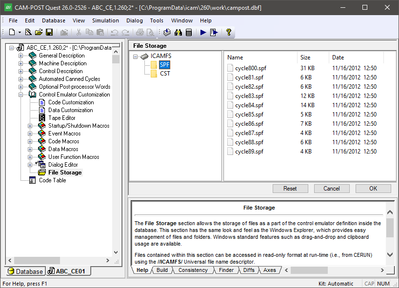
The File Storage Facility
The file storage section is organized with a directory browser on the left hand side of the main working window and a detailed file listing on the right hand side. Selecting a directory in the left hand window will display the contents of that directory in the right hand window. Use the right-mouse context sensitive pop-up window to add, rename or delete directories and files. You can drag and drop directories and files from an external file system into the file storage view. You can also drag and drop files and directories within the file storage facility to move or copy files. Standard Windows conventions apply for all drag and drop operations. Any operations performed in the File Storage facility will have no effect on the original files that reside in the external file system.
The OK button saves changes and exits the File Storage facility. The Cancel button exits the File Storage facility ignoring any changes that may have been made. The Reset button also undoes any changes that may have been made, but keeps the File Storage facility active.
The File Storage section can be used as follows:
A macro OPEN command (see “Opening a Text File (OPEN)” can reference a file in the internal File Storage for read-only purposes. Specify an absolute file path for the filename using an “//ICAMFS/” universal file descriptor (e.g., “//ICAMFS/toolno.dat”).
A macro DECLAR/EXTERN,FUNCTN command (see “External Functions”) can reference a DLL or Python file in the internal File Storage that contains the user function code to execute. Specify an absolute file path for the filename using an “//ICAMFS/” universal file descriptor (e.g., “//ICAMFS/mycode.dll” or “//ICAMFS/mycode.py”).
A macro SYSTEM command (see “Calling other programs (SYSTEM)”) can reference an EXE file in the internal File Storage that contains the program to execute. Specify an absolute file path for the filename using an “//ICAMFS/” universal file descriptor (e.g., “//ICAMFS/myprogram.exe”).
A subprogram startup macro (see “Subprogram Startup/Shutdown Macros”) can reference a subprogram definition file in the internal File Storage by setting the $P9 macro variable to the absolute path of the subprogram as shown above for the OPEN macro command.
The File Storage facility initially stores all of its data in memory while you are editing a control emulator. The data is later stored in the database in a compressed format when Saving or Generating. CERUN uncompresses the entire File Storage section into memory when the control emulator is later run.