Simulation»
Simulation»
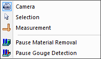
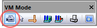
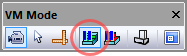
When the Camera mode menu bar selection is active, holding the left-mouse button down while moving the mouse changes the orientation of the camera. The cursor appears as a four-way arrow when in Camera mode. This mode can also be activated by selecting the circled button in the VM Mode toolbar above. While in Camera mode, you can press and hold the Ctrl key to temporarily switch to Selection mode. This can be used to quickly select objects to rotate about or to attach the camera to.
There are two types of camera rotation.
The default rotation is to keep the camera position fixed but to change where the camera is aimed. This is similar to how we rotate our head to look around a scene.
You can hold the Shift key to change how the camera rotates. When Shift is pressed, the camera rotates around a point in space. This rotation point is by default the center of the world or the selected VM Grid object, but can be changed by selecting any object and choosing Simulation»
Camera» Pivot (Ctrl P). As a quick shortcut, double-clicking an object in a simulation window will set that object as the Pivot center and fit the object in the window.
If you prefer the second form of camera rotation by default, clear the
“Default to Look-Around camera” checkbox in the Simulation»
Simulation»
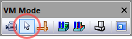
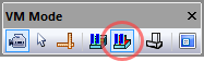
When the Selection mode menu bar selection is active, pressing the left-mouse button selects the object under the mouse pointer. The cursor appears as a simple arrow when in Selection mode. Thus mode can also be activated by selecting the circled button in the VM Mode toolbar above. While in Selection mode, you can press and hold the Ctrl key to temporarily switch to Camera mode. This can be used to get a better view of the object you are trying to select.
Selection mode is useful when developing models with QUEST, or to select
objects to make them transparent, or to hide selected objects using the
Simulation»
Simulation»
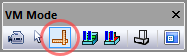
When the Measurement mode menu bar selection is active, pressing the left-mouse button selects the object under the mouse pointer for measurement purposes. Measurements can be taken between any objects, including in-process stock. The cursor appears as an arrow with calipers when in Measurement mode and measurement results are shown in the simulation window in the form of a small HUD (heads-up display). Measurement mode can also be activated by selecting the circled button in the VM Mode toolbar above. While in Measurement mode, you can press and hold the Ctrl key to temporarily switch to Camera mode. The ESC key repeatedly undoes selections.
The VM Measure toolbar (available when in measurement mode) provides
various buttons to define the type of measurement, the types of objects
being measured, and chained vs. fanned measuring options. See
“Simulation»
The VM Cross Section toolbar can be used to obtain a cross section view
of the in-process stock, which can facilitate measurement of normally
hidden features or measurements taken in the section plane. See
“Simulation»
Simulation»
When the “Pause Material Removal” menu bar selection is active, the in-process stock and machinable fixtures will not be affected by the cutting action of the tool. This function temporarily disables material removal simulation (MRS). This MRS setting can also be toggled by selecting the circled button in the VM Mode toolbar above.
Temporarily inhibiting MRS can be useful to ignore further invalid
cutting actions of a tool, during the early simulation phase of a
manufacturing program. Also, when used with Run»
Simulation»
When the “Pause Gouge Detection” menu bar selection is active, interference (i.e., collisions) will no longer be diagnosed between the cutting tool and the design part. This mode can also be toggled by selecting the circled button in the VM Mode toolbar above.
Temporarily inhibiting tool/